

1. Introduction
2. Implementation of Molten Salt Properties
3. Verification of CUPID-MSR
4. Investigation of Conceptual MSR Fluid Design
5. Conclusions
1. Introduction
Interest in Molten Salt Reactors (MSRs) has increased significantly in recent years due to their liquid-fuel characteristics and enhanced safety features. In this type of reactor, nuclear fuel is dissolved in molten salt and circulated throughout the primary loop, unlike in widely used light-water reactors (LWRs), where the fuel remains solid. The operating temperature of the molten fuel reaches up to 700°C, allowing for high thermal efficiency and favorable economic performance. Most importantly, MSRs are characterized by improved passive safety features. In an emergency, the molten salt fuel can be drained, either by the operator’s action or passively, into dedicated drain tanks to achieve a subcritical geometry, effectively halting the event’s progression.
Historically, the first nuclear reactor to use molten salts was the Aircraft Reactor Experiment (ARE) [1], built in 1954 at Oak Ridge National Laboratory (ORNL), US, and designed to power a nuclear-propelled bomber. Although the aircraft nuclear propulsion program was eventually abandoned, ORNL later achieved first criticality with the Molten- Salt Reactor Experiment (MSRE) [2] in 1965. This 8 MWth test reactor, fueled by LiF-BeF2-ZrF4-UF4, operated successfully for 4.5 years before shutting down in 1969. The MSRE was widely considered a success, demonstrating the viability of molten salt fuels despite significant corrosion issues with structural materials. Nevertheless, MSR development in the US was halted due to a shift in focus toward other reactor designs. Since then, no other MSRs have been constructed worldwide for several decades.
Currently, no MSR is in operation worldwide, but MSRs are considered a promising alternative to water-cooled reactors. This is evident from the numerous MSR projects under development globally. Notable examples include Terrestrial Energy’s IMSR-400 (Canada) [3], Kairos Power’s KP-FHR (USA) [4], and Saltfoss Energy’s Compact Molten Salt Reactor (Denmark) [5]. South Korea is also advancing MSR development. The Korea Atomic Energy Research Institute (KAERI) is developing the Korea Molten Salt Reactor (K-MSR) [6,7], a 100 MWth reactor intended for marine propulsion. Furthermore, in 2024, KAERI signed a Memorandum of Understanding with Saltfoss Energy to collaborate on MSR technology development [8].
Reactor concepts using non-water coolants require novel designs and enhanced safety strategies. Due to their unconventional characteristics, a thorough safety analysis is essential, which requires the use of validated simulation codes. Since most nuclear power plants use light water as a coolant, widely used codes such as RELAP5 [9], CATHARE [10], and MARS [11] are specific to such systems and are not suitable for the analysis of MSRs. Therefore, new simulation tools are required. To address this gap, KAERI developed the system code GAMMA [12] for designs using non-water coolants, including MSRs [13,14]. The above-mentioned codes are known as system codes, as they simulate the entire reactor system, including major components using simplified one-dimensional models.
LWR cores consist of axial channels with predominantly one-directional coolant flow, which allows 1D codes to model the flow adequately. In contrast, MSRs typically do not have internal structures like fuel assemblies and control rods. This is especially true for fast-spectrum MSRs, which also lack solid axial moderators such as graphite. As a result, radial flow becomes significant alongside axial flow, leading to turbulent mixing within the reactor vessel. Therefore, more accurate 3D codes are necessary to address the thermal hydraulics in the reactor vessel of MSRs.
For this reason, CUPID-MSR was developed, incorporating molten salt properties into the CUPID code [15,16]. CUPID is a component-scale thermal-hydraulics code developed by KAERI since 2011. It was initially designed for transient two-phase flow analysis in LWRs, based on a two-fluid model. It can be used as a component or CFD-porous, or a computational fluid dynamics (CFD) code, depending on the computational resolution. Recently, more attention has been given to supporting fluids beyond water, including molten salts.
At present, CUPID-MSR includes two salt mixtures: uranium-potassium-chloride (U-K-Cl) and uranium-sodium-magnesium-chloride (U-Na-Mg-Cl) compounds. In MSRs, the use of fuel as both the fissile material and coolant leads to a strong coupling between neutronics and thermal-hydraulics. This includes feedback coefficients and the transport of delayed neutron precursors and fission products. Therefore, MSR modeling requires the use of neutron kinetics and thermal-hydraulics codes as a multi-physics package. Although CUPID provides a multi-physics coupling with a 3D neutron kinetics code [17], its application is currently limited to LWRs, since 3D neutron kinetics codes are not available for MSRs at present. With the coupling with a MSR neutronics code, CUPID-MSR is expected to support the design of new MSR systems.
To verify the accuracy of molten salt applications of CUPID-MSR, the code is tested against an established benchmark problem. For this purpose, the thermal cavity problem proposed by De Vahl Davis [18] is used and compared with results obtained from CUPID for both types of molten salt. Additionally, a preliminary design of a conceptual MSR is examined by varying the vessel diameter and the number of openings on the inlet disk, focusing on flow mixing and maximum local temperature.
Section 2 outlines the implementation of molten salt properties in CUPID-MSR. Code verification is presented in Section 3, followed by an investigation of the conceptual MSR design in Section 4. A summary and the main conclusions of the present study are provided in Section 5.
2. Implementation of Molten Salt Properties
CUPID adopts the two-fluid model [15] for transient two-phase flow analysis of LWRs such as APR1400 [17]. In CUPID, the equations of state were originally implemented for light water (H2O). The governing equations are discretized using the finite volume method (FVM) with unstructured mesh. These linearized equations are then solved by semi-implicit or fully-implicit numerical schemes, depending on the specific application. A more detailed description of the governing equations, equations of state, numerical methods used in CUPID, and the CUPID-MSR extension can be found in previously published studies [15,17].
In this study, CUPID-MSR has been developed for application to MSRs, where the working fluid is molten salt rather than light water. Among the various molten salts currently considered for MSRs, two types of molten salt property models were implemented in CUPID-MSR. The first is a U-K-Cl compound and the second candidate is a U-Na-Mg-Cl compound. The eutectic temperature of the U-Na-Mg-Cl compound is known to be lower than that of the U-K-Cl compound. Equations of state for the U-K-Cl and U-Na-Mg-Cl compounds have been implemented in CUPID-MSR, allowing the specific working fluid to be activated via an input parameter.
Material properties for both salt compounds have been implemented in CUPID-MSR using a separate material properties table file. These properties vary with temperature, and this dependency is represented through equations used to calculate density, heat capacity, thermal conductivity, and dynamic viscosity of a given salt compound, as described below.
The density of a compound is computed using empirical linear models for the density of each pure component , expressed as:
where and are empirical constants, and is the temperature. The molar volume contribution of each component in the compound is given by the following expression:
where and denote the mole fraction and molar mass of component , respectively. Their product corresponds to the mass contribution of that component. The final expression for the density of the entire salt mixture is given as follows.
The heat capacity of a compound is calculated using a polynomial model for each component , which is dependent on temperature, and is expressed as:
where , , , , and are empirical constants. The final expression for the heat capacity of the mixture is given as follows.
where is the product of the mole fraction and the molar heat capacity of component .
Thermal conductivity is expressed similarly to the density calculation, using a temperature-dependent linear model for each component , given by:
where is the current temperature, and is the melting point of component . The overall thermal conductivity of the compound is computed as the sum of the weighted contributions of each component , as follows.
The dynamic viscosity of the mixture is calculated based on the dynamic viscosity of each component , using the following expression.
where is the ideal gas constant, equal to . The dynamic viscosity of the mixture is calculated as:
3. Verification of CUPID-MSR
The molten salt properties of CUPID-MSR have been verified using a 2D thermal cavity problem originally proposed by De Vahl Davis [18]. Fig. 1 shows the schematic of the thermal cavity problem. The square cavity (H = W) is oriented such that gravity acts perpendicular to its surface. Constant wall temperature conditions were imposed on the left and right walls. Higher temperature is assigned for the left surface. Adiabatic boundary condition is applied to the top and bottom surfaces. A natural circulation flow is expected inside the cavity due to the buoyancy force.
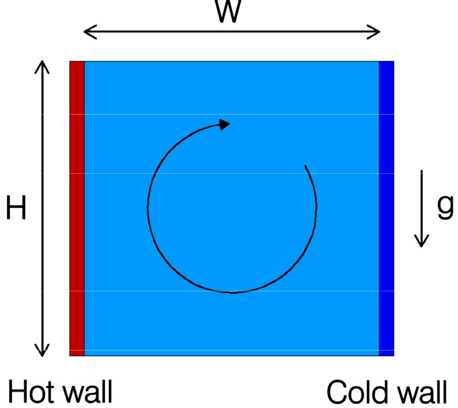
In this thermal cavity problem, the formation of natural circulation is governed by the Rayleigh number (), defined by the following equation.
where are fluid density, expansion coefficient, viscosity, and gravity, respectively. is the Prandtl number defined as , where is specific heat and is thermal conductivity. As the Rayleigh number increases, the fluid flow tends to transition from laminar to turbulent. In this study, the calculations were performed for , where the flow remains in laminar condition. Different values are tested, as the material properties described in Section 2 vary with changes in . The hot and cold surface temperatures were set to 900.5 K and 899.5 K, respectively. The computational mesh used was 40×40 for cases with , and 80×80 for higher values of . Since a coarse mesh produces distorted solutions at high , a finer mesh must be used for these cases compared to low cases, as described in the reference data. The computational mesh is presented in Fig. 2, which shows the structured 40×40 mesh used for low calculations. The cavity size was adjusted to achieve the desired Rayleigh number, as summarized in Table 1.

Table 1.
Cavity size and mesh resolution
| (U-K-Cl compound) | 0.00732 | 0.01578 | 0.03399 | 0.07322 |
| (U-Na-Mg-Cl compound) | 0.00806 | 0.01737 | 0.03743 | 0.08063 |
| Mesh resolution | 40×40 | 40×40 | 80×80 | 80×80 |
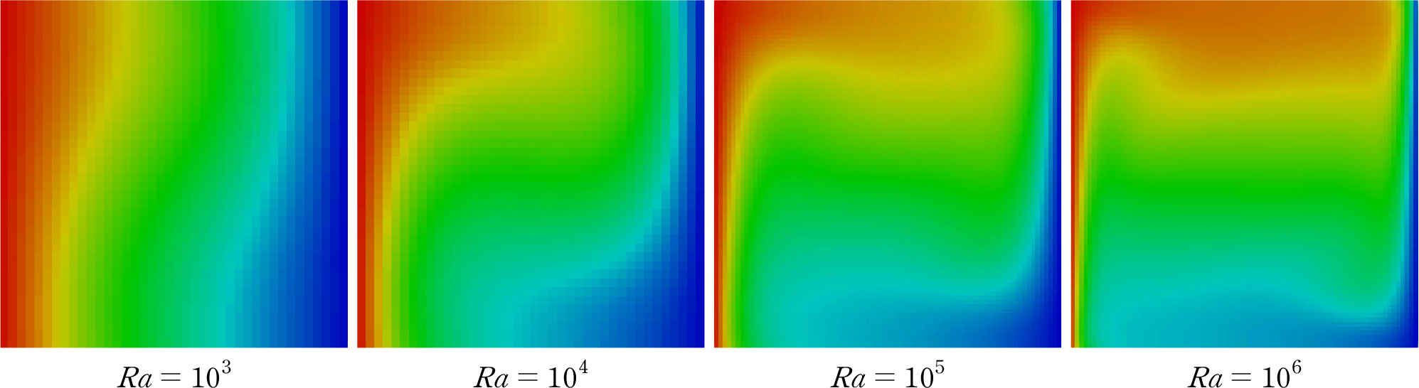
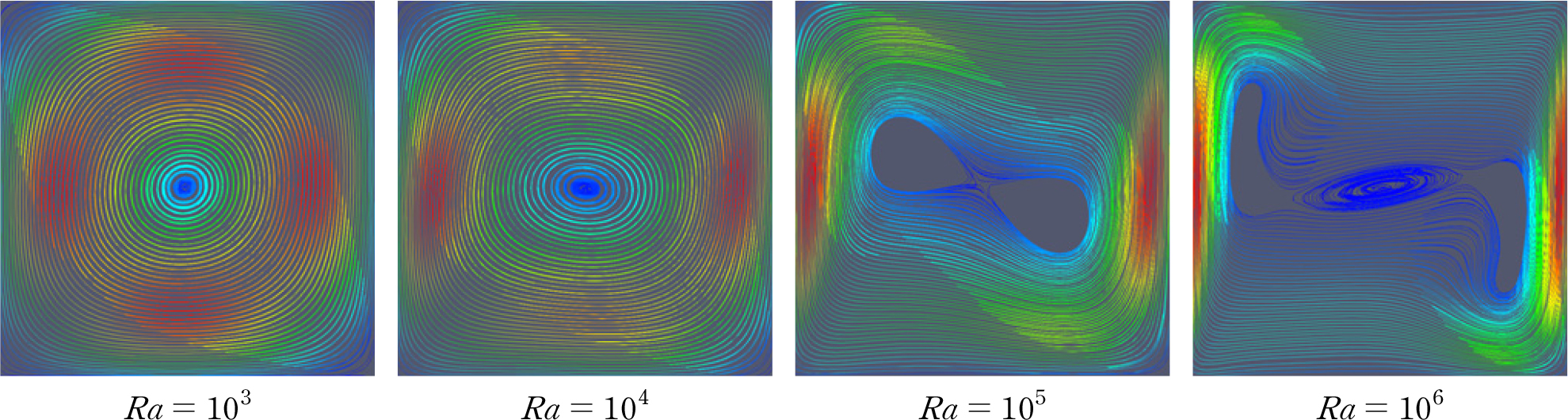
Figs. 3 and 4 show the calculated fluid temperature distributions and fluid motions for different numbers when the working fluid is the U-K-Cl compound. The results indicate that natural circulation develops in the clockwise direction. The fluid circulation intensifies as increases, resulting in the formation of more flow vortices. According to Fig. 4, the number of flow vortices is 1 for , 2 for , and 3 for . As shown in Fig. 3, the thermal boundary layer thickness decreases due to the stronger circulation flow. This enhances heat transfer at both the hot and cold surfaces. The heat transfer near the hot surface can be quantified by the Nusselt number () as follows.
where . If a non-dimensional temperature is used, it can be expressed as follows.
Subsequently, the average heat transfer rate at the hot surface can be determined by integrating the local along the y-direction.
Eq. (28) can be approximated using Simpson’s rule as follows.
The average Nusselt number () at the hot surface is calculated using Eq. (29) and compared with the results of De Vahl Davis in Tables 2 and 3 for the U-K-Cl and U-Na-Mg-Cl compounds, respectively. The difference from the solution by De Vahl Davis ranges from 0.12% to 8.34% for the U-K-Cl compound, and from 1.89% to 5.95% for the U-Na-Mg-Cl compound. The difference between the two solutions are minimal (<2.5%) for , when the flow is fully laminar. However, the difference increases as the fluid flow approaches the turbulent flow condition. Additionally, the temperature contours and streamlines closely resemble those in the De Vahl Davis benchmark.
Table 2.
Comparison of Nusselt number predictions by the CUPID-MSR for the U-K-Cl compound
| Calculation | ||||
| Nusselt number at hot surface | ||||
|
De Vahl Davis (FDM) | 1.118 | 2.243 | 4.519 | 8.8 |
|
CUPID-MSR (FVM) |
1.1193 (0.12)* |
2.2237 (0.86)* |
4.3051 (4.73)* |
8.0663 (8.34)* |
4. Investigation of Conceptual MSR Fluid Design
MSRs are considered competitive among Small Modular Reactors (SMRs) due to their unique design features, which enable relatively simple reactor design and enhanced safety. In MSRs, nuclear fuel is dissolved in molten salt, whereas commercial LWRs adopt a complicated solid fuel assembly design. In addition to fuel assemblies, LWRs require control element assemblies (CEA) to moderate fast neutrons, since only thermal neutrons, which move more slowly than fast neutrons, are involved in nuclear fission. Current MSR designs usually adopt a fast neutron spectrum, eliminating the need for internal structures used for the neutron moderation. This simplifies reactor design significantly. Another important feature of MSRs is their operation at higher coolant temperature under atmospheric pressure, in contrast to Pressurized Water Reactors (PWRs), which require system pressure of around 150 bars.
One of the conceptual MSR design is investigated by analyzing the fluid flow inside the reactor vessel using the CUPID-MSR code. It is a fast neutron spectrum MSR design with a thermal power of 6 MW and, therefore, does not include internal structures. As a preliminary design, a horizontal cylinder type reactor vessel has been proposed, as depicted in Fig. 5. The working fluid is a molten salt of the U-K-Cl compound. The reactor vessel is a horizontal cylinder surrounded by a reflector, which prevents neutron leakage from the core. The length of the reactor vessel is 2 meters, and three different diameters, 35 cm, 40 cm, and 45 cm, are examined. Since there are no internal structures inside the reactor vessel, the fluid velocity can become very low in certain regions due to recirculation, which may lead to the formation of local hot spots. The objective of the fluid analysis is to identify an optimal design that minimizes low flow regions and consequently maintains the local temperature as close as possible to the outlet temperature, as the maximum local temperature should not significantly exceed the outlet temperature.
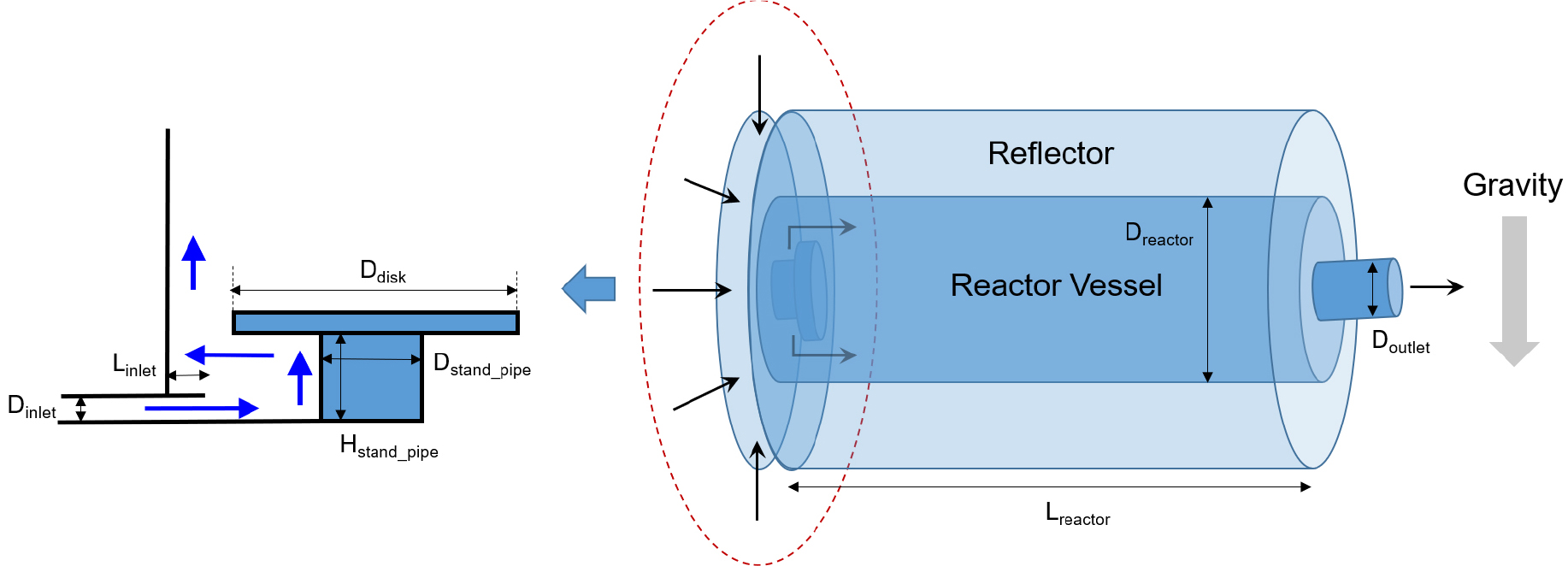
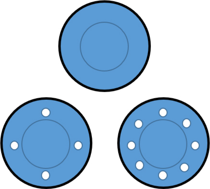
An inlet flow distribution device was installed, as shown in Fig. 5, to minimize flow recirculation in the reactor vessel. An inlet mass flow of 421 kg/s is introduced through the circumferencial gap, and the inlet temperature of the U-K-Cl compound is set to 620°C. To enhance flow mixing in the reactor vessel, small circular openings are introduced on the inlet disk, as illustrated in Fig. 6, with the number of openings set to 0, 4, and 8.
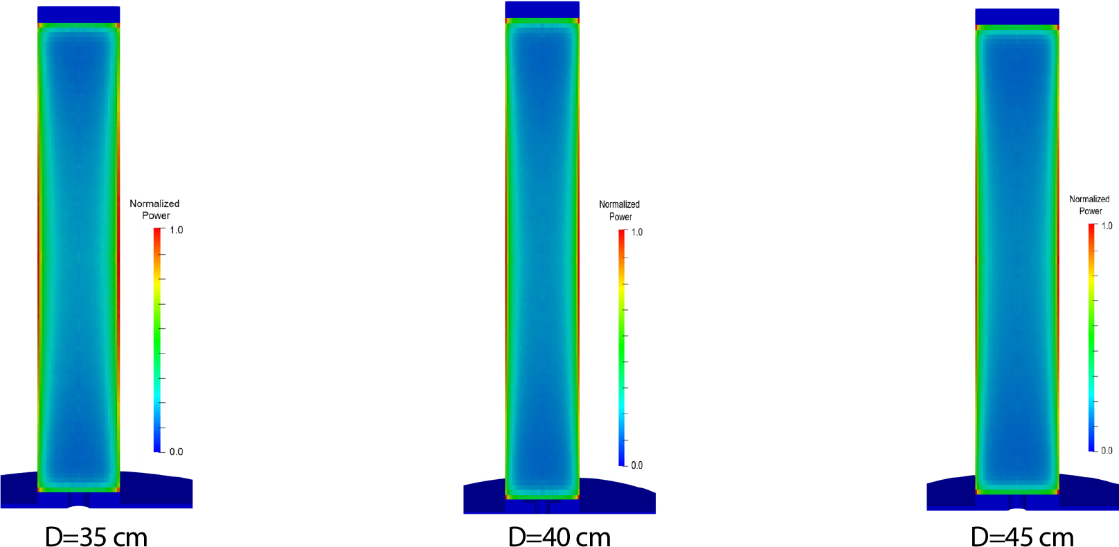
Thermal flow mixing and the maximum local temperature in the proposed MSR reactor were investigated using CUPID-MSR. Analyses were conducted for nine cases with varying reactor diameters and different numbers of openings on the inlet disk, as summarized in Table 4. The reactor power distributions for 35 cm, 40 cm, and 45 cm diameter reactors are shown in Fig. 7. These distributions were obtained from 3-dimensional neutron kinetics calculations. The reactor power is higher near the reflector, where more nuclear fission occurs due to thermal neutrons produced by the reflector. Ideally, a multi-physics coupled calculation of thermal hydraulics and neutron kinetics is required to accurately determine the power profile, since nuclear fission power is affected by the fluid density. However, in this study, the reactor power distribution is approximated by neglecting the fluid density feedback effect.
Table 4.
Analysis cases
| Reactor diameter (cm) | Case ID | Number of openings |
| 35 | D35O0 | 0 |
| D35O4 | 4 | |
| D35O8 | 8 | |
| 40 | D40O0 | 0 |
| D40O4 | 4 | |
| D40O8 | 8 | |
| 45 | D45O0 | 0 |
| D45O4 | 4 | |
| D45O8 | 8 |
Structured meshes are generated as shown in Fig. 8, where two-dimensional meshes are extruded along the axial direction. The numbers of computational meshes are 141,840, 158,112, and 181,440 for reactors with diameters of 35 cm, 40 cm, and 45 cm, respectively.
Each reactor design was tested to evaluate the maximum fluid temperature inside the reactor vessel and to assess flow stability. Fig. 9 shows the fluid temperature distribution for each case considered, while Table 5 summarizes the results. Out of all the cases, five cases developed stable flow, while the other five were unstable. In all cases without openings on the inlet disk, the flow was unstable and reached the highest local temperatures compared to cases with any number of openings. The highest local temperature (695°C) was recorded for the design with a reactor diameter of 45 cm and no inlet disk openings.
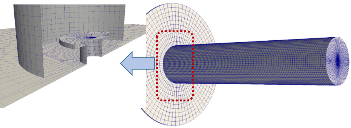
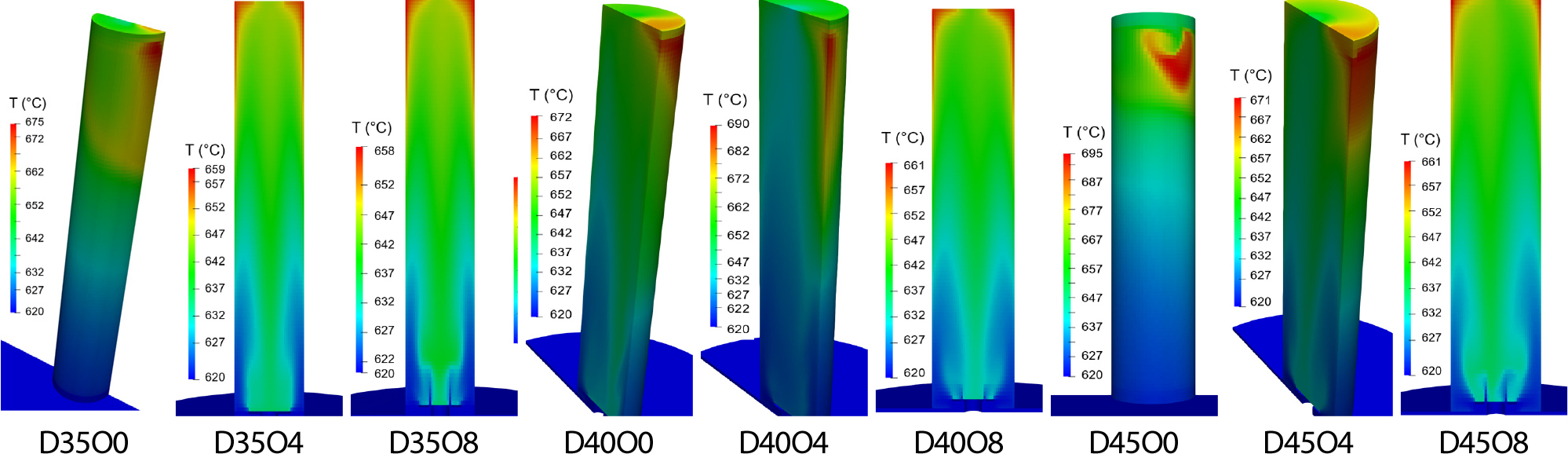
Table 5.
Maximum temperature and flow stability across design cases
Generally, the lowest local temperatures were observed in the cases with 8 openings: D35O8, D40O8, and D45O8, with corresponding temperatures of 658°C, 661°C, and 661°C, respectively. The differences in maximum local temperatures among the three reactor diameter cases are within 3°C, and all exhibit stable flow conditions. Therefore, it can be concluded that, as long as there are 8 openings on the inlet disk, the reactor diameter has no significant effect on maximum local temperature.
Flow instability results from reduced mixing within the vessel and formation of low-velocity and recirculation zones, which lead to the development of hot spots. In cases without openings, the flow instability is larger due to increased obstruction at inlet disk and the absence of alternative flow paths. The fluid is forced to turn sharply around the corners of the inlet plenum and the inlet disk, which further contributes to flow instability.
Additionally, in this cylindrical reactor vessel design, the highest local temperatures were observed at the corners of the top vessel plate, due to the reactor outlet being smaller in diameter than the vessel itself. The elevated temperatures in this region result from the formation of recirculation and low-velocity zones, which must be considered in the final reactor design.
5. Conclusions
This paper describes the implementation of molten salt properties in the nuclear thermal-hydraulics code CUPID-MSR. This enhancement supports the thermal-hydraulic design of emerging molten salt reactor concepts, which currently lack dedicated simulation tools for reactors using these fluids. CUPID-MSR is an extension of the CUPID code that incorporates the thermophysical properties of liquid salts and employs specially adapted governing equations and numerical methods to simulate these fluids with high accuracy. The current implementation supports two eutectic molten salt mixtures: U-K-Cl and U-Na-Mg-Cl compounds.
The accuracy of the molten salt implementation in CUPID-MSR was verified against the widely recognized De Vahl Davis benchmark, which involves a thermal cavity with natural circulation driven by buoyancy forces. The resulting Nusselt numbers for various Rayleigh numbers are in close agreement with the original De Vahl Davis data. The difference from the reference solution ranges from 0.12% to 8.34% for the U-K-Cl compound, and from 1.89% to 5.95% for the U-Na-Mg-Cl compound, confirming the accuracy of the results. Moreover, the difference between the two solutions remains minimal in the fully laminar flow ( ), staying below 2.5%.
As part of the evaluation of CUPID-MSR, a conceptual design of a horizontal cylinder-type fast neutron spectrum MSR was investigated. A total of nine cases were tested, with reactor diameters of 35 cm, 40 cm, and 45 cm. For each diameter, configurations with 0, 4, or 8 inlet disk openings were evaluated. The cases with 8 openings consistently demonstrated flow stability and effective mixing, resulting in the lowest local maximum temperatures, ranging from 658°C to 661°C. The differences in maximum temperature among the reactor diameters with 8 openings were negligible. In contrast, all cases without openings on the inlet disk showed unstable flow and the highest local maximum temperatures among all configurations, ranging from 672°C to 695°C, depending on the reactor diameter. These results highlight the importance of proper inlet disk design and demonstrate the advantage of incorporating 8 openings compared to 4, and an even greater advantage compared to 0 openings.
Overall, the results from both tests demonstrate that the implementation of molten salt in CUPID-MSR has been successful, confirming its reliability as a simulation tool. For further development of CUPID-MSR, additional types of molten salt fluids can be incorporated, given the wide range of proposed salts, each with distinct thermophysical properties. Furthermore, as shown in the conceptual MSR design investigation presented in this paper, CUPID-MSR can be utilized for developing new MSR designs and for improving the design discussed. Additionally, due to strong feedback coefficients existing between neutronics and thermal-hydraulics, coupling CUPID-MSR with an MSR neutronics code into a single multi-physics package should be considered for future development.
