1. 서 론
2. 펌프 형상 및 작동 조건
3. Trailing edge tubercle 설계 및 최적화 기법
4. 수치 해석 기법
5. 결과 및 분석
5.1 Sinusoidal tubercle trailing edge 최적화 결과
5.2 Separate height tubercle trailing edge 최적화 결과
6. 결 론
1. 서 론
펌프는 전 세계 전동기에서 소모되는 에너지 소모량의 가장 큰 비율인 22%를 차지하고 있다[1,2]. 따라서 펌프 효율 향상은 환경적, 경제적으로 가치가 크다. 펌프의 성능을 향상시키 위해 오랜 기간 동안 펌프 부품들의 형상 최적화 연구들이 수행되어 왔었다. 임펠러 blade 개수의 최적화 연구에서는 blade 개수에 따른 펌프의 효율과 진동을 관찰하고 최적의 개수를 구하였다[3,4,5,6,7]. Blade angle에 관한 연구에서는 임펠러의 rotation angle[8]와 blade wrap angle[9,10], 임펠러와 디퓨저 blade의 inlet, outlet angle[11]에 따른 최적화를 수행하였다. Trailing edge의 최적화 연구에서는 모양과 두께를 바꿔가며 펌프의 효율과 pressure pulsation, shedding vortex을 분석하였다[12,13,14,15,16,17,18,19].
추가적인 발전을 위해서는 다른 획기적인 방법의 필요성이 대두되었고, 생체모방공학의 활용을 생각해 볼 수 있다. 혹등고래의 지느러미 leading edge에 있는 tubercle은 항력을 감소시킨다고 알려져 있다. 여러 연구들은 airfoil과 turbine 날개의 leading edge에 tubercle 모양을 적용한 결과 유동 박리가 줄어들어서 항력이 감소하고, 양항비가 증가하며 실속이 방지되는 것으로 나타났다[20,21,22,23,24,25,26]. 펌프 부품에 생체 모방 공학을 적용한 연구들도 존재한다. 디퓨저의 guide vane의 leading edge에 tubercle 모양을 적용한 연구와[27,28,29], volute tongue에 tubercle을 적용한 연구에서[30,31], vortex와 separation의 감소, 압력 진동과 에너지 손실을 감소시킨 결과를 얻었다. 임펠러 trailing edge에 sine 파 형태의 tubercle 형상을 적용한 연구가 수행된 바 있는데, 압력 진동과 shedding vortex가 감소한 결과를 얻었다[32,33,34]. 그러나 펌프 효율 향상의 결과는 보이지 않았고, 총 3가지 형상에 대해서만 분석을 진행하여서, tubercle 형상 인자의 분석과 최적화 연구는 부족한 상황이다.
따라서 본 연구에서는 생체 모방 형상을 활용한 원심 펌프 임펠러 trailing edge의 최적화 연구를 수행하였다. 혹등고래의 tubercle 형상을 인자 기반 설계를 통해 trailing edge에 적용했고, 펌프의 효율 기반 최적화를 진행하였다. 최적화는 두 단계로 진행되었으며, 먼저 sine 파 모양의 tubercle 최적화와, 이 결과를 바탕으로 tubercle의 개별 높이를 조절하며 최적화를 진행하여 혹등고래 tubercle의 생체모방공학적 특성을 더 잘 반영할 수 있게 하였다. 설계 인자별 펌프 성능과 유동장에 미치는 경향을 분석하였고, 최종적으로 가장 높은 성능을 보이는 최적 형상을 도출하였다.
2. 펌프 형상 및 작동 조건
본 연구에 사용된 펌프는 두크(Dooch Inc.)에서 제공한 모델이며, 작동 조건 및 형상 인자들은 Table 1에 기술되어 있다. 3단 펌프지만 빠르고 단순한 설계 최적화를 위해 1단 펌프 영역에 대해 유동 해석 및 최적화를 수행했다. 유동 해석에 사용한 계산 영역의 형상은 Fig. 1(a)에서 볼 수 있다.
Table 1.
Main parameters of centrifugal pump
|
Parameter
|
Value
|
|
Design flow rate Qd(m3/h)
|
200
|
|
Design rotating speed nd(rpm)
|
3570
|
|
Design head Hd(m)
|
54
|
|
Specific speed ns(metric units)
|
42.2
|
|
Impeller blade number, Z |
6
|
|
Impeller inlet diameter D1(mm)
|
113
|
|
Impeller outlet diameter D2(mm)
|
187
|
|
Blade inlet angle β1 |
25°
|
|
Blade outlet angle β2 |
22°
|
|
Blade wrap angle φ |
123°
|
|
Blade outlet width b(mm)
|
24
|
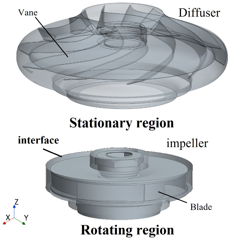
Fig. 1.
Computational domain and grid interface of impeller and diffuser regions
3. Trailing edge tubercle 설계 및 최적화 기법
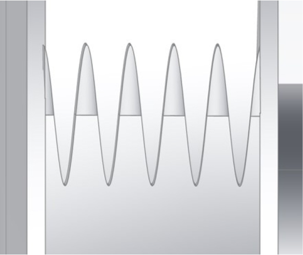
생체 모방 형상은 상대적으로 형상적 자유도가 높아 설계 인자 숫자가 과다해질 수 있으며 최적 설계시 복잡성 증가의 원인이 된다. 이 문제점을 고려하여 본 연구에서는 trailing edge tubercle에 대하여 두 단계로 최적 설계를 진행하였다. 첫번째 단계에서 임펠러의 trailing edge 부분에 두개 인자 기반의 sinusoidal tubercle을 적용하여 설계를 진행하였다. Fig. 2(a)와 같이 기존 임펠러 blade의 직선형 trailing edge를 기준으로 sine 파 형태의 tubercle을 적용하였다. 설계 변수로는 tubercle의 높이와 개수를 나타내는 amplitude()와 wavenumber()로, wavenumber는 trailing edge 전체 폭(=24 mm)에 들어가는 sine 파 주기의 개수와 같다. Sine 파 형상의 공식은 식 (1)이며, trailing edge의 중심선을 기존 임펠러 blade의 직선형 trailing edge와 일치하도록 설계를 진행하였다. Fig. 2(b)는 3가지 다른 sine 파를 보여준다. 기존의 sinusoidal 형태의 trailing edge 연구들은 tubercle의 개수가 정수 값이 되도록, sine 파의 wavelength(λ)를 정수 값으로만 설정되었다[32,33,34]. 본 연구에서는 두 설계 변수 amplitude와 wavenumber가 정수 값뿐만 아니라 범위 내에서 연속적인 값이 되도록 설정하였다. 따라서 sampling 과정에서 변수의 고른 분포와, surrogate model을 통한 최적화를 더 용이하게 하였다. 설계 변수의 범위는 =0-8 mm, =3-8이다.
Design of experience(DOE)에서는 Sobol sequence sampling를 사용하여 샘플들을 생성하였다. Sinusoidal tubercle 최적화에서는 80개의 샘플들이 사용되었다. Surrogate model로는 Kriging model을 사용하였다.
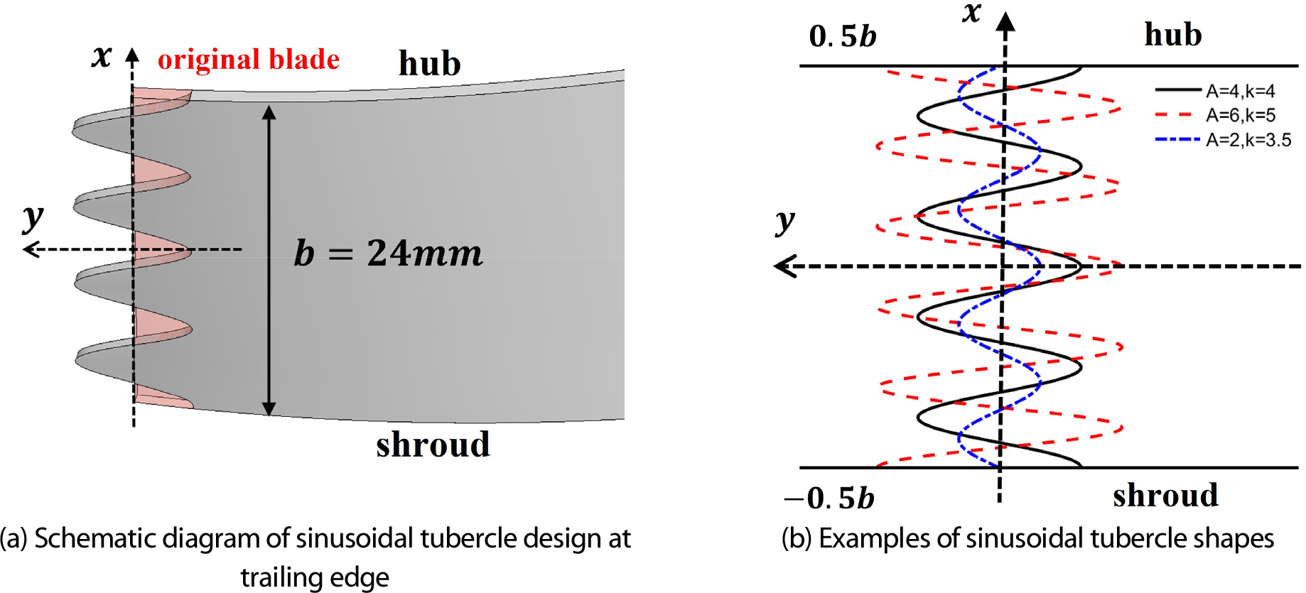
Fig. 2.
Configuration and examples of sinusoidal tubercle at impeller trailing edge
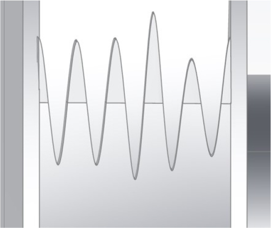
두번째 단계에서 sinusoidal tubercle을 기반으로 separate height tubercle의 설계를 진행하여 체계적 최적화를 수행하였다. 혹등고래의 tubercle을 관찰하였을때, 각각의 tubercle들의 길이가 다르고, flipper의 tip으로 갈수록 크기가 감소하는 경향이 보였다[35,36]. 이러한 tubercle의 특성을 고려하여 높이를 개별로 조절하는 최적화 연구는 임펠러 trailing edge에 적용하여 진행된 바가 없다. Sinusoidal tubercle의 최적 형상은 는 7.80 mm, 는 4.93이고 5.1절에서 결과를 볼 수 있다. 이 형상을 바탕으로 개별 높이 변수들의 설계를 진행하였고, 설계를 용이하게 하기 위해 Fig. 3(a)와 같이 는 8 mm, 는 5로 근사시켜서 기준을 삼았다. Tubercle의 설계는 Fig. 3(b)와 같이 양쪽 끝의 tubercle은 높이를 고정시키고, 가운데 4개 tubercle의 높이를 설계 변수로 설정하였다. 설계 변수의 이름은 hub에서 shroud까지 순서대로 h1, h2, h3, h4이다. 전체 blade의 chord length와 면적을 유지하기 위하여, tubercle 사이의 깎이는 영역의 깊이는 양쪽 tubercle 돌출부 높이의 평균값으로 설정하였다. Tubercle의 curve는 cubic polynomial spline interpolation으로 tubercle의 끝점들을 이어서 만들었다. 설계 변수의 범위는 sinusoidal tubercle의 최적 형상의 tubercle 높이 8 mm에서 50% 범위인 4-12 mm로 설정하였다. Separate height tubercle 최적화에서는 설계 변수가 많기 때문에 350개의 샘플이 사용되었다.
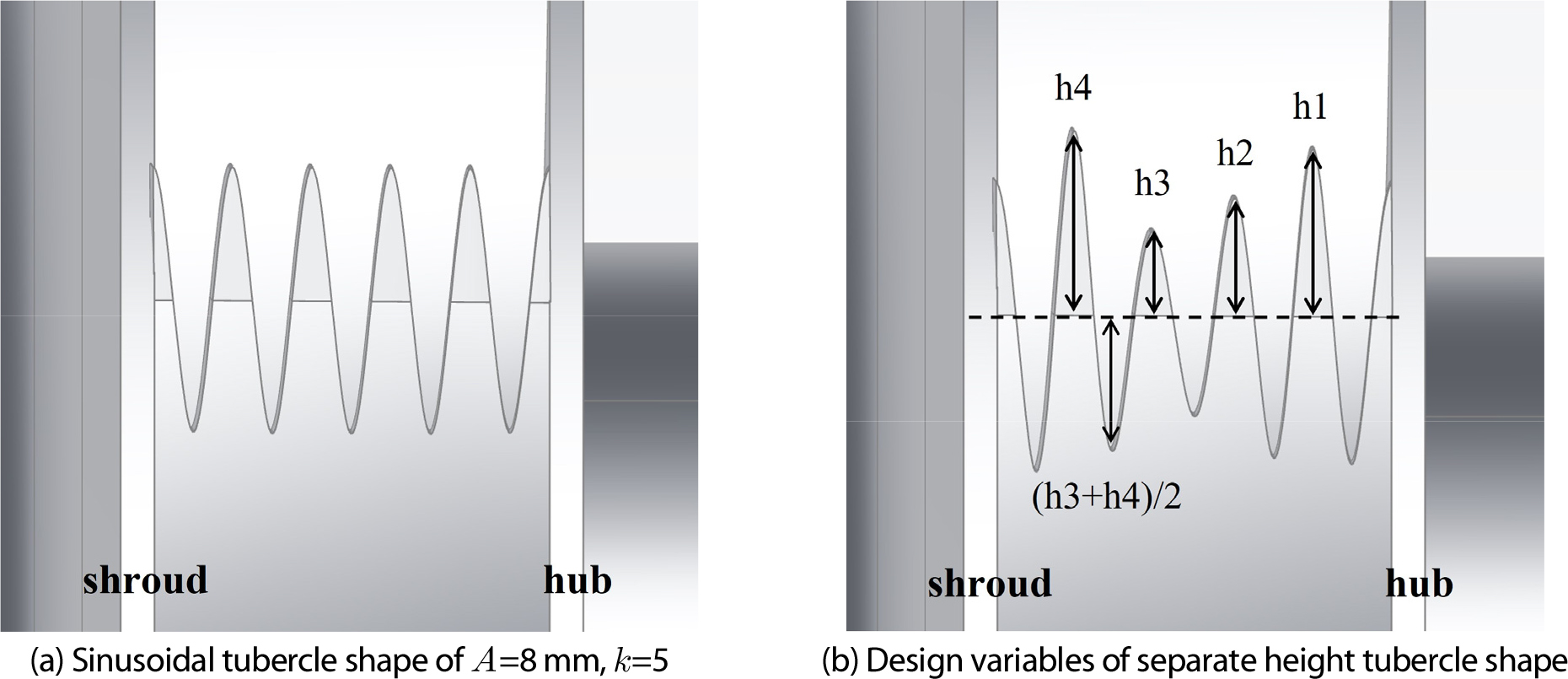
Fig. 3.
Configuration of separate height tubercle at impeller trailing edge
최적화를 위한 목적 함수로 설계점(1.0Qd)과 탈설계점에서의 성능을 모두 고려하여 식 (2)의 복합 효율을 사용하였다. 1.0Qd와 0.7Qd 유량에서의 효율의 가중 합을 사용하였고, 설계점 효율의 가중치를 0.7로 더 많이 부여하였다.
여기서 𝜌, , , , 𝜔는 각각 유체 밀도, 중력 가속도, 펌프 수두, 축 토크, 회전 각속도이다.
4. 수치 해석 기법
유동 해석에는 Siemens STAR-CCM+ V17.02가 사용되었다. 정상 상태, 비압축성 난류 유동의 지배방정식은 다음과 같다.
여기서 는 mean velocity, 는 Cartesian coordinate, 는 mean pressure, 𝜈는 kinematic viscosity, 는 turbulent viscosity이다. RANS 모델로는 shear stress transport(SST) k-ω 난류 모델이 사용되었다. SST k-ω 모델은 k-ω 모델과 k-ε 모델 대비 벽 근처 유동뿐 아니라 경계층에서 멀리 떨어진 유동도 잘 예측할 수 있다. 또한 adverse pressure gradient로 인한 유동 박리도 잘 예측할 수 있다. 따라서 많은 유체 기계 연구에서 사용되어왔고 개선된 결과를 보여주었다[37,38]. 임펠러를 포함한 rotating region에 회전 좌표계를 적용해서 moving reference frame(MRF)을 사용하였다. 입출구는 periodic interface로 고정 유량 조건이 부가되었다. 벽면에서의 경계 조건은 점착 조건이다. 작동 유체는 상온 상태의 물이며 밀도는 998 kg/m3, 점도는 0.889 cP이다.
격자는 다면체 격자를 사용하였으며 trailing edge의 효과를 더 정확히 측정하기 위해 Fig. 4(a)와 같이 trailing edge 영역과 임펠러의 wake region에 더 조밀한 격자를 생성하였다. Fig. 4(a)의 아래쪽 그림은 기존 trailing edge와 Fig. 2(b)의 3가지 다른 설계 변수의 tubercle 격자 형상을 보여준다. 임펠러 trailing edge 경계층 근처의 격자는 Fig. 4(b)와 같고, 벽 모델로 all-y+ model을 사용했으며 임펠러 blade 벽에서 y+값은 10-30이다. 격자 수렴 테스트는 격자 개수에 따른 효율을 기준으로 수행하였다. 벽 근처 및 내부 격자 크기를 변경하여 진행한 결과 Fig. 5와 같이 380만의 격자 개수에서 효율과 수두의 수렴을 보였고, 유동 해석을 위하여 380만 개의 격자가 채택되었다.
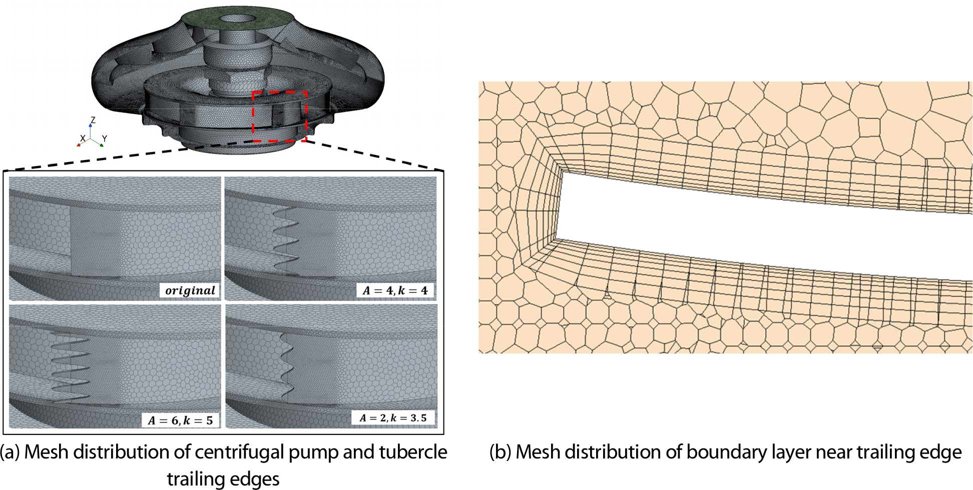
Fig. 4.
Mesh distribution of centrifugal pump and boundary layer near tubercle trailing edges
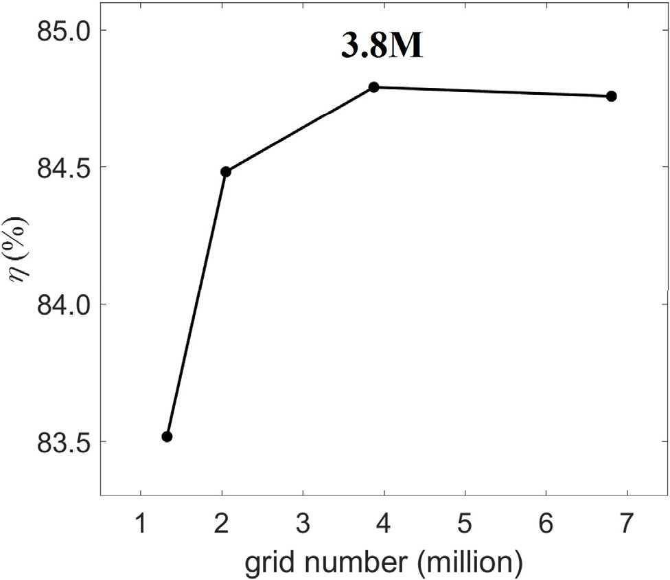
Fig. 5.
Results of grid convergence study
유량 1.0Qd 조건에서 예측된 펌프 효율은 84.80%로 실험 측정값인 81.15%와 다소 차이를 보였다. 입구 경계 조건의 차이를 감안하면 적절한 범위의 오차로 생각된다.
5. 결과 및 분석
5.1 Sinusoidal tubercle trailing edge 최적화 결과
먼저 sinusoidal tubercle trailing edge에 대한 최적화를 수행하였다. 효율과 동시에 난류 운동 에너지(TKE)도 같이 평가하여, tubercle trailing edge가 펌프 성능과 난류 유동에 미치는 영향을 분석하였다. TKE는 난류 섭동의 세기를 나타내며, 난류 모델에서 계산된 modeled TKE 값을 측정하였다. 측정한 위치는 Fig. 6와 같이 유동이 디퓨저로 들어가기 전인 trailing edge의 하류 지역에서 평면에서 평균한 값을 관찰하였다.
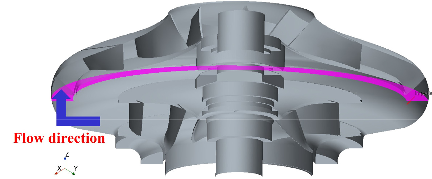
Fig. 6.
Plane region to evaluate turbulent kinetic energy
Fig. 7은 1.0Qd에서 sinusoidal tubercle의 효율과 TKE 결과이다. Tubercle trailing edge를 적용했을 때 기본 임펠러와 비교하여 효율이 증가하였음을 볼 수 있다. 설계 변수에 따른 영향으로는, amplitude와 wavenumber가 커질수록 효율이 증가하는 경향을 보였고, 특히 amplitude의 영향을 크게 받았다. TKE는 기본 임펠러에 비해 tubercle trailing edge를 적용했을 때 감소하였으며, 이는 trailing edge에 serration과 tubercle을 적용했을 때 소음과 진동이 감소하는 기존 연구의 결과와 일치하였다[39,40,41,42,43,44,45]. 설계 변수에 따라서는 효율의 경향성과 같이 amplitude와 wavenumber가 커질수록 TKE가 감소하였다. 두 결과의 상관관계를 scatter plot을 그려보면 Fig. 8(a)와 같이 negative correlation을 보이고, 이는 TKE의 감소가 효율의 향상으로 이어졌음을 보여준다.
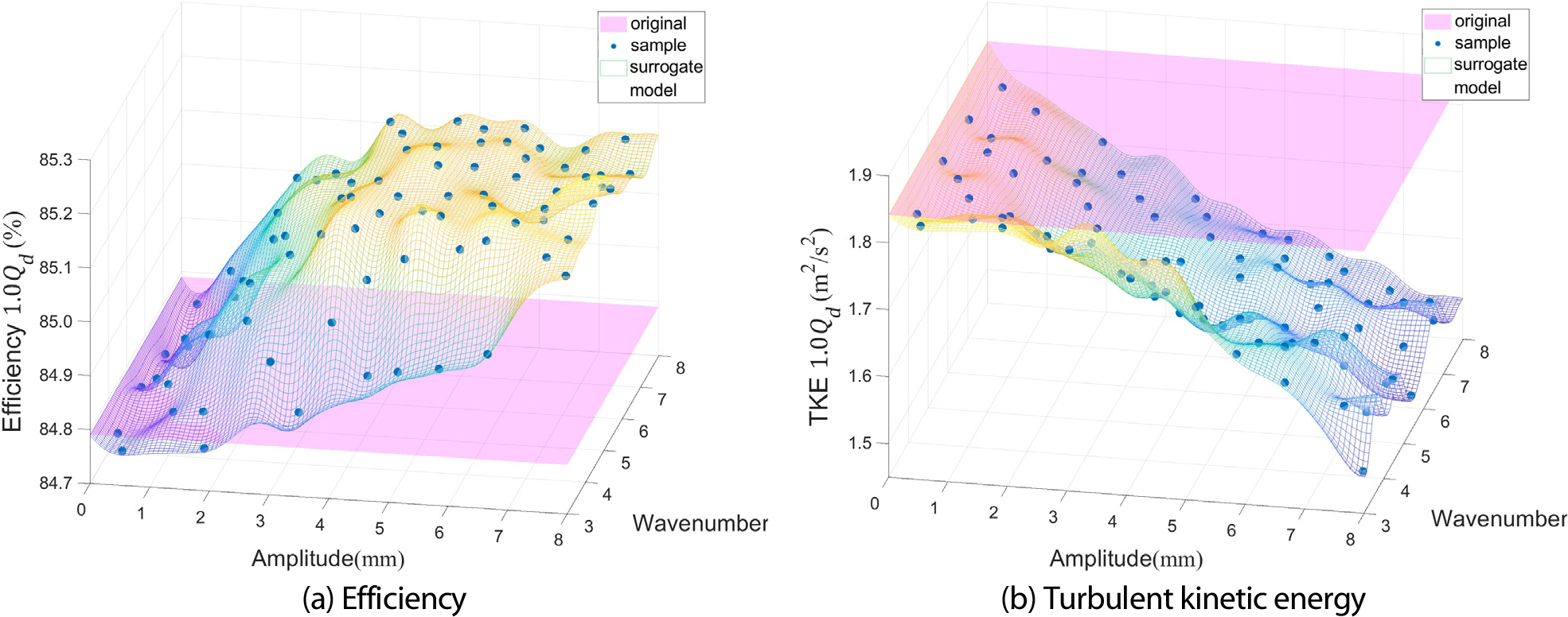
Fig. 7.
Distribution of efficiency and TKE at sample points for sinusoidal tubercle trailing edge with 1.0Qd
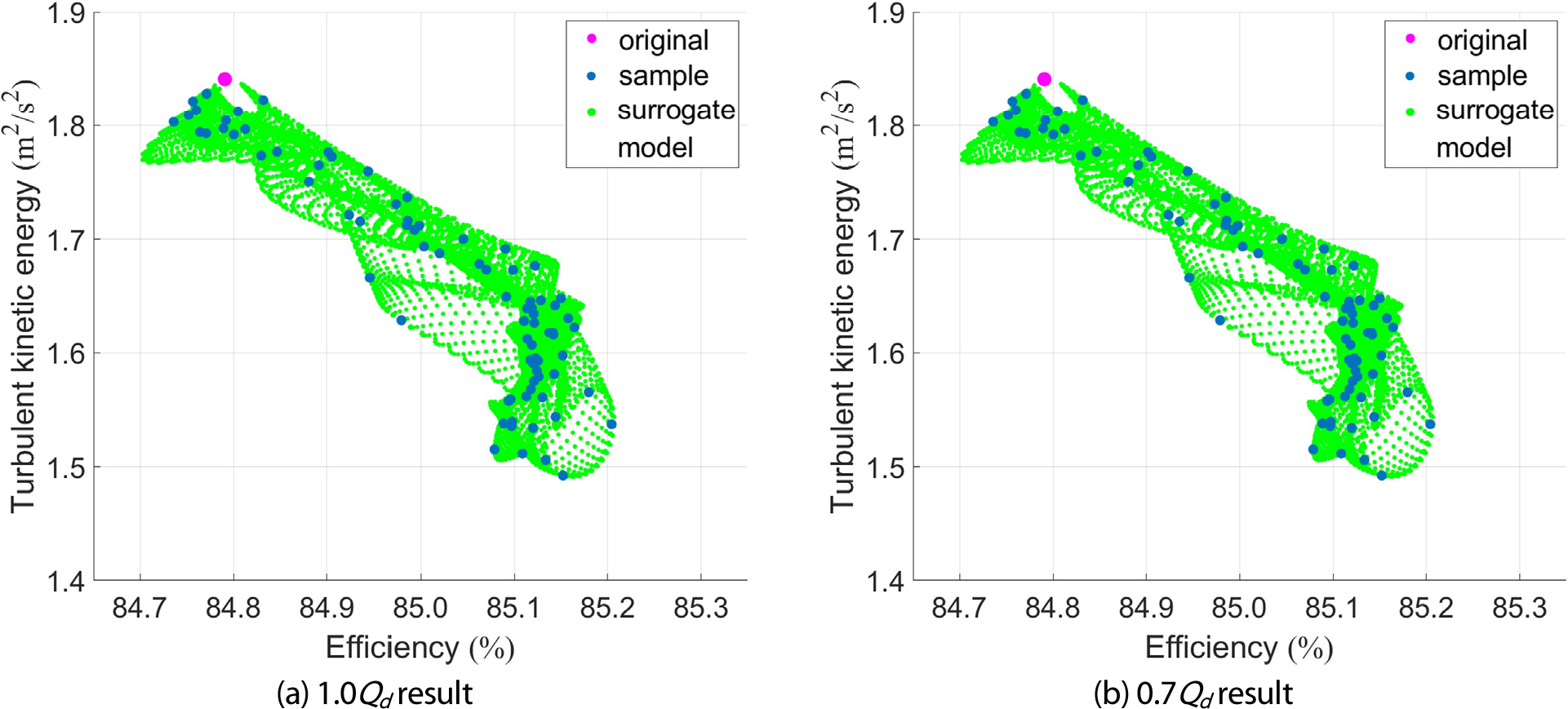
Fig. 8.
Scatter plot of efficiency and TKE from sinusoidal tubercle trailing edge samples
Table 2와 3은 각각 1.0Qd, 0.7Qd와 복합 효율 조건에서 최적화 형상 및 성능 결과를 보여준다. 1.0Qd의 가중치가 0.7로 더 크게 설정되어서 복합 효율 결과가 1.0Qd에서의 결과와 비슷하게 나타났다. 복합 효율 기준 0.66% 증가하였고, 1.0Qd에서 효율이 0.48%, 0.7Qd에서 1.09% 증가하였다. 이 최적 형상을 바탕으로 =8 mm, =5로 근사시켜 separate height tubercle 설계의 기준으로 삼았다.
Table 2.
Tubercle shape and performance at optimal points with different flow rates
|
Case
|
Tubercle shape
|
Design variable
|
Efficiency
|
|
1.0Qd |  | A=7.84 mm
k=4.97
|
85.21%
(+0.41%)
|
|
0.7Qd | | A=7.84 mm
k=7.95
|
76.46%
(+1.05%)
|
5.2 Separate height tubercle trailing edge 최적화 결과
Sinusoidal tubercle의 최적 형상을 바탕으로 separate height tubercle의 설계를 진행하고, 총 350개의 샘플들에 대하여 최적화를 진행하였다. Fig. 9는 샘플들의 유량별 효율을 4개 tubercle의 설계 변수(h1∼h4) 별로 분석한 결과이다. 효율 기준 상대적으로 두번째 tubercle(h2)의 영향에 일관성이 관찰되며 민감도가 큰 것이 관찰되었다. Fig. 6의 임펠러 하류 지역에서 TKE를 측정하여 효율과의 상관관계를 분석하였고, 그 결과는 Fig. 10에서 보여준다. Sinusoidal tubercle 최적화 결과와 유사하게 효율이 증가하면서 TKE가 감소하는 관계를 보여준다. 복합 효율을 기준으로 가장 높은 효율을 보인 최적 형상과 효율 및 TKE의 결과는 Table 4에 기술되어 있다. 복합 효율 기준 0.73% 증가하였고, 1.0Qd에서 효율이 0.61%, 0.7Qd에서 0.99% 증가하였다. Table 3의 sinusoidal tubercle의 최적화 결과와 비교하였을 때 복합 효율과 1.0Qd에서의 효율이 더 증가하였고, separate height tubercle 설계를 적용함으로써 약간의 추가적인 성능 향상을 얻을 수 있었다.
Table 3.
Tubercle shape and performance with optimized composite objective function
|
Optimal sinusoidal tubercle
|
Design variable
|
Efficiency
|
 | A=7.80 mm
k=4.93
| |
82.64%
(+0.66%)
|
|
85.27%
(+0.48%)
|
|
76.50%
(+1.09%)
|
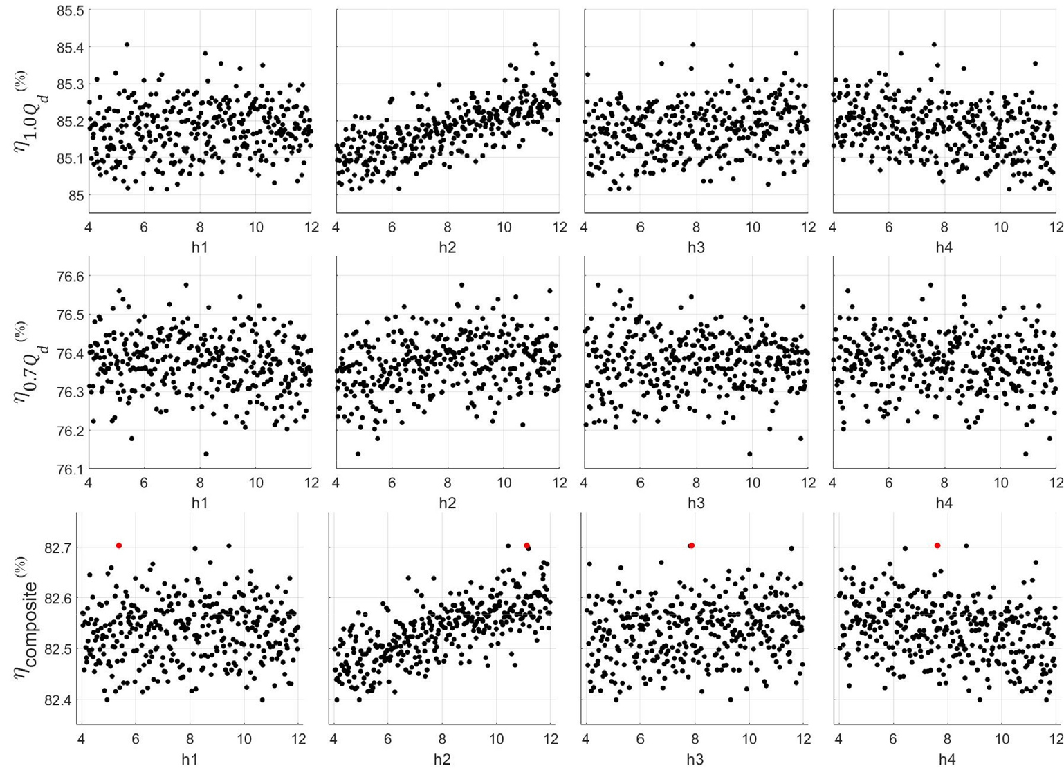
Fig. 9.
Efficiency values versus design variables from separate height tubercle samples
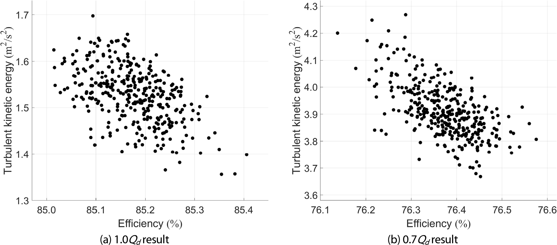
Fig. 10.
Scatter plot of efficiency and TKE from separate height tubercle samples
Table 4.
Tubercle shape and performance with optimized composite objective function
|
Optimal separate height tubercle
|
Design variable
|
Result
|
 | h1=5.38 mm
h2=11.13 mm
h3=7.88 mm
h4=7.63 mm
| |
82.70%
(+0.73%)
|
|
85.41%
(+0.61%)
|
|
76.40%
(+0.99%)
|
|
2.18 m2/s2
(-17.7%)
|
|
1.40 m2/s2
(-24.0%)
|
|
4.00 m2/s2
(-11.6%)
|
이 최적 형상에 대하여 다른 유량에 대해서도 평가하여 성능 향상을 확인하였다. Fig. 11은 기존 임펠러와 separate height tubercle의 최적 형상을 적용한 임펠러에 대하여 0.2Qd부터 1.4Qd까지의 효율을 비교한 결과이다. 0.2Qd부터 1.1Qd까지는 기존 임펠러에 비해 효율이 증가하였고, 1.1Qd보다 큰 유량에서는 감소하였다. 효율은 0.8Qd에서 최대 1.8% 증가하였고, 효율이 증가한 구간에서는 평균 0.8% 증가하였다. 설계점에서는 0.61% 증가한 것과 비교하여 탈설계점에서 효율이 더 많이 증가하였고, 설계점 뿐 아니라 전체 유량 범위에서 tubercle trailing edge가 성능 향상에 효과적임을 확인할 수 있다.
임펠러를 통한 유동 제어 결과 디퓨저 입구 유동에 대한 영향이 가능하다. 볼루트를 통해 큰 각도로 회전하는 특성상 입구 유동각에 대한 영향은 작다고 판단되어 난류 강도를 비교했다. 1.0Qd에서 디퓨저 입구 기준 기존 임펠러와 separate height tubercle의 최적 형상을 적용한 임펠러의 TKE 값은 각각 1.84 m2/s2와 1.40 m2/s2로 약 24% 감소함을 관찰했다. 유동 제어 영향이 디퓨저 입구 유동에도 영향이 있음을 알 수 있다.
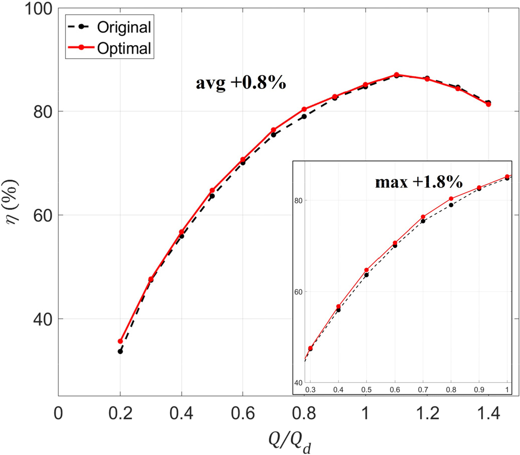
Fig. 11.
Efficiency curves of original and optimized impellers for different flow rates
6. 결 론
본 연구에서는 생체 모방 기반의 tubercle 형상을 원심 펌프 임펠러 trailing edge에 적용하여 최적화를 수행하고 유동장을 분석하여 tubercle의 유동 제어가 성능 향상에 미치는 원인을 분석하였다. 최적화는 두 단계로 진행되었으며, sine 파 형태의 tubercle의 최적화와 이 결과를 바탕으로 tubercle의 개별 높이를 조절한 최적화를 수행하였다. 최적화의 목적함수로는 두 유량 값에서의 복합 효율을 사용하였으며, Sobol sequences를 사용하여 샘플들을 생성하여 평가하였고 Kriging surrogate model을 사용하여 최적 형상을 탐색하였다. 임펠러 trailing edge에 tubercle 형상을 적용했을 때 기존 펌프에 비해 효율이 증가하고 TKE가 감소하였다. 두 결과는 음의 상관관계를 보여 TKE의 감소가 효율의 증가로 이어지는 결과를 보여주었다. Separate height tubercle에서는 두번째 tubercle이 결과에 영향을 가장 크게 미쳤으며 높이가 클수록 효율이 증가하였다. 최적 형상은 기존 펌프에 비해 설계점(1.0Qd)에서 효율이 0.61% 증가하였고, 최대 0.8Qd에서 1.8%, 평균 0.8% 증가하여 탈설계점 조건에서 효율이 더 많이 증가하고, 전체 유량 구간에서 성능 향상에 효과적임을 확인했다.
후속 연구 관련 본 연구에서는 다수 케이스 해석 기반 최적 설계에 집중하여 LES를 수행하지 않았지만 유동장 및 메커니즘 분석을 위해 추후 연구에서 진행할 필요가 있다. 또한 펌프 진동 및 소음 관련 영향도 연구 필요성이 있다.
Acknowledgements
이 성과는 산업통상자원부 및 산업기술기획평가원(KEIT)의 지원에 의한 연구임(No. 20015994, 소재부품기술개발사업). 또한 정부(과학기술정보통신부)의 재원으로 한국연구재단의 지원을 받아 수행된 연구임(No. 2022R1F1A107493111).
References
2016, Arun Shankar, V.K., Umashankar, S., Paramasivam, S. and Hanigovszki, N., "A comprehensive review on energy efficiency enhancement initiatives in centrifugal pumping system," Appl. Energy, Vol.181, pp.495-513.
10.1016/j.apenergy.2016.08.0702019, Mandhare, N.A., Karunamurthy, K. and Ismail, S., "Compendious review on "Internal flow physics and minimization of flow instabilities through design modifications in a centrifugal pump," J. Pressure Vessel Technol., Vol.141, No.5, 051601.
10.1115/1.40433832012, Yang, S.S., Kong, F.Y., Qu, X.Y. and Jiang, W.M., "Influence of blade number on the performance and pressure pulsations in a pump used as a turbine," J. Fluids Eng., Vol.134, No.12, 124503.
10.1115/1.40078102019, Abo Elyamin, G.R.H., Bassily, M.A., Khalil, K.Y. and Gomaa, M.S., "Effect of impeller blades number on the performance of a centrifugal pump," Alexandria Engng. J., Vol.58, No.1, pp.39-48.
10.1016/j.aej.2019.02.0042019, Subroto and Effendy, M., "Optimization of centrifugal pump performance with various blade number," AIP Conf. Proc., Vol.2114, No.1, 020016
10.1063/1.51124002020, Yu-qin, W. and Ze-wen, D., "Influence of blade number on flow-induced noise of centrifugal pump based on CFD/CA," Vacuum, Vol.172, 109058.
10.1016/j.vacuum.2019.1090582022, Sakran, H.K., Abdul Aziz, M.S., Abdullah, M.Z. and Khor, C.Y., "Effects of blade number on the centrifugal pump performance: A review," Arab. J. Sci. Eng., Vol.47, No.7, pp.7945-7961.
10.1007/s13369-021-06545-z2020, Liu, Y., Han, Y., Tan, L. and Wang, Y., "Blade rotation angle on energy performance and tip leakage vortex in a mixed flow pump as turbine at pump mode," Energy, Vol.206, 118084.
10.1016/j.energy.2020.1180842014, Tan, L., Zhu, B., Cao, S., Bing, H. and Wang, Y., "Influence of blade wrap angle on centrifugal pump performance by numerical and experimental study," Chin. J. Mech. Eng-en., Vol.27, No.1, pp.171-177.
10.3901/CJME.2014.01.1712018, Han, X., Kang, Y., Li, D. and Zhao, W., "Impeller optimized design of the centrifugal pump: A numerical and experimental investigation," Energies, Vol.11, No.6, p.1444.
10.3390/en110614442018, Liu, M., Tan, L. and Cao, S., "Design method of controllable blade angle and orthogonal optimization of pressure rise for a multiphase pump," Energies, Vol.11, No.5, p.1048.
10.3390/en110510482016, Gao, B., Zhang, N., Li, Z., Ni, D. and Yang, M., "Influence of the blade trailing edge profile on the performance and unsteady pressure pulsations in a low specific speed centrifugal pump," J. Fluids Eng., Vol.138, No.5, 051106.
10.1115/1.40319112019, Binama, M., Su, W.T., Cai, W.H., Li, X.B., Muhirwa, A., Li, B. and Bisengimana, E., "Blade trailing edge position influencing pump as turbine (PAT) pressure field under part-load conditions," Renew. Energ., Vol.136, pp.33-47.
10.1016/j.renene.2018.12.0772019, Zhang, N., Liu, X., Gao, B., Wang, X. and Xia, B., "Effects of modifying the blade trailing edge profile on unsteady pressure pulsations and flow structures in a centrifugal pump," Int. J. Heat Fluid Flow, Vol.75, pp.227-238.
10.1016/j.ijheatfluidflow.2019.01.0092020, Cui, B., Zhang, C., Zhang, Y. and Zhu, Z., "Influence of cutting angle of blade trailing edge on unsteady flow in a centrifugal pump under off-design conditions," Appl. Sci., Vol.10, No.2, p.580.
10.3390/app100205802023, Li, H., Chen, Y., Yang, Y., Wang, S., Bai, L. and Zhou, L., "CFD simulation of centrifugal pump with different impeller blade trailing edges," J. Marine Sci. Engng., Vol.11, No.2, p.402.
10.3390/jmse110204022023, Cui, B., Sun, F., Zhang, Y., Liu, J. and Xiao, J., "Influence of blade trailing edge profile on unsteady pressure pulsations in a multistage centrifugal pump," Energy Sci. & Engng., Vol.11, No.4, pp.1471-1483.
10.1002/ese3.14042023, Ding, H., Lin, F., Chang, T. and Ge, F., "Numerical study on the effect of blade trailing edge filing on performance and unsteady pressure pulsation in low specific speed centrifugal pump," J. Vibration Engng. Tech., Vol.12, No.1, pp.233-245.
10.1007/s42417-022-00840-12024, Song, Z., Chen, Y., Yu, T., Wang, X., Cao, H., Li, Z., Lang, X., Xu, S., Lu, S. and Jiang, C., "Influence of the trailing edge shape of impeller blades on centrifugal pumps with unsteady characteristics," Processes, Vol.12, No.3, p.508.
10.3390/pr120305082004, Miklosovic, D.S., Murray, M.M., Howle, L.E. and Fish, F.E., "Leading-edge tubercles delay stall on humpback whale (Megaptera novaeangliae) flippers," Phys. Fluids, Vol.16, No.5, pp.L39-L42.
10.1063/1.16883412007, Miklosovic, D.S., Murray, M.M. and Howle, L.E., "Experimental evaluation of sinusoidal leading edges," J. Aircraft, Vol.44, No.4, pp.1404-1408.
10.2514/1.303032011, Yoon, H.S., Hung, P.A., Jung, J.H. and Kim, M.C., "Effect of the wavy leading edge on hydrodynamic characteristics for flow around low aspect ratio wing," Comput. Fluids, Vol.49, No.1, pp.276-289.
10.1016/j.compfluid.2011.06.0102011, Favier, J., Pinelli, A. and Piomelli, U., "Control of the separated flow around an airfoil using a wavy leading edge inspired by humpback whale flippers," Comptes Rendus. Mécanique, Vol.340, No.1-2, pp.107-114.
10.1016/j.crme.2011.11.0042015, Wei, Z., New, T.H. and Cui, Y.D., "An experimental study on flow separation control of hydrofoils with leading-edge tubercles at low Reynolds number," Ocean Eng., Vol.108, pp.336-349.
10.1016/j.oceaneng.2015.08.0042016, Shi, W., Rosli, R., Atlar, M., Norman, R., Wang, D. and Yang, W., "Hydrodynamic performance evaluation of a tidal turbine with leading-edge tubercles," Ocean Eng., Vol.117, pp.246-253.
10.1016/j.oceaneng.2016.03.0442022, Ke, W., Hashem, I., Zhang, W. and Zhu, B., "Influence of leading-edge tubercles on the aerodynamic performance of a horizontal-axis wind turbine: A numerical study," Energy, Vol.239, 122186.
10.1016/j.energy.2021.1221862019, Zhiwei, G., Chihang, W., Zhongdong, Q., Xianwu, L. and Weipeng, X., "Suppression of hump characteristic for a pump-turbine using leading-edge protuberance," Proc. Inst. Mech. Eng. Part A J. Power Energy, Vol.234, No.2, pp.187-194.
10.1177/09576509198546382022, Liu, H., Wang, X., Lu, Y., Yan, Y., Zhao, W., Wu, X. and Zhang, Z., "Application and optimal design of the bionic guide vane to improve the safety serve performances of the reactor coolant pump," Nucl. Eng. Technol., Vol.54, No.7, pp.2491-2509.
10.1016/j.net.2022.01.0312023, Zhao, Y., Li, D., Chang, H., Fu, X., Wang, H. and Qin, D., "Suppression effect of bionic guide vanes with different parameters on the hump characteristics of pump-turbines based on entropy production theory," Energy, Vol.283, 128650.
10.1016/j.energy.2023.1286502020, Lin, P., Song, P., Zhu, Z. and Li, X., "Research on the rotor-stator interaction of centrifugal pump based on sinusoidal tubercle volute tongue," J. Appl. Fluid Mech., Vol.14, No.2, pp.589-600.
2023, Lin, P., Wang, C., Song, P. and Li, X., "Analysis of the energy loss and performance characteristics in a centrifugal pump based on sinusoidal tubercle volute tongue," Entropy, Vol.25, No.3, p.545.
10.3390/e250305452019, Li, B., Li, X., Jia, X., Chen, F. and Fang, H., "The role of blade sinusoidal tubercle trailing edge in a centrifugal pump with low specific speed," Processes, Vol.7, No.9, p.625.
10.3390/pr70906252021, Lin, Y., Li, X., Li, B., Jia, X. and Zhu, Z., "Influence of impeller sinusoidal tubercle trailing-edge on pressure pulsation in a centrifugal pump at nominal flow rate," J. Fluids Eng., Vol.143, No.9, 091205.
10.1115/1.40506402022, Lin, Y., Li, X., Zhu, Z., Wang, X., Lin, T. and Cao, H., "An energy consumption improvement method for centrifugal pump based on bionic optimization of blade trailing edge," Energy, Vol.246, 123323.
10.1016/j.energy.2022.1233231995, Fish, F.E. and Battle, J.M., "Hydrodynamic design of the humpback whale flipper," J. Morphol., Vol.225, No.1, pp.51-60.
10.1002/jmor.10522501052011, Fish, F.E., Weber, P.W., Murray, M.M. and Howle, L.E., "The tubercles on humpback whales' flippers: Application of bio-inspired technology," Integr. Comp. Biol., Vol.51, No.1, pp.203-213.
10.1093/icb/icr0162019, Pei, J., Zhang, F., Appiah, D., Hu, B., Yuan, S., Chen, K. and Asomani, S.N., "Performance prediction based on effects of wrapping angle of a side channel pump," Energies, Vol.12, No.1, p.139.
10.3390/en120101392020, Maleki, A., Ghorani, M.M., Haghighi, M.H.S. and Riasi, A., "Numerical study on the effect of viscosity on a multistage pump running in reverse mode," Renew. Energ., Vol.150, pp.234-254.
10.1016/j.renene.2019.12.1131991, Howe, M.S., "Aerodynamic noise of a serrated trailing edge," J. Fluid. Struct., Vol.5, No.1, pp.33-45.
10.1016/0889-9746(91)80010-B2013, Azarpeyvand, M., Gruber, M. and Joseph, P., "An analytical investigation of trailing edge noise reduction using novel serrations," 19th AIAA/CEAS Aeroacoustics Conference, 2009.
2019, Tang, H., Lei, Y. and Fu, Y., "Noise Reduction Mechanisms of an Airfoil with Trailing Edge Serrations at Low Mach Number," Appl. Sci., Vol.9, No.18, p.3784.
10.3390/app91837842019, Li, D., Liu, X., Hu, F. and Wang, L., "Effect of trailing-edge serrations on noise reduction in a coupled bionic aerofoil inspired by barn owls," Bioinspiration & Biomimetics, Vol.15, No.1, 016009.
10.1088/1748-3190/ab529e2021, Kholodov, P. and Moreau, S., "Optimization of trailing-edge serrations with and without slits for broadband noise reduction," J. Sound Vibration, Vol.490, 115736.
10.1016/j.jsv.2020.1157362022, Lu, Z., Zhang, F., Jin, F., Xiao, R. and Tao, R., "Influence of the hydrofoil trailing-edge shape on the temporal-spatial features of vortex shedding," Ocean Eng., Vol.246, 110645.
10.1016/j.oceaneng.2022.1106452023, Singh, S.K. and Narayanan, S., "Control of airfoil broadband noise through nonuniform sinusoidal trailing- edge serrations," Phys. Fluids, Vol.35, No.2, 025139.
10.1063/5.0133556

