

1. Introduction
2. Methodology
2.1 Computational Setup and Boundary Conditions
2.2 Meshing Strategy and Post-Processing
3. Analysis Model
3.1 Atmospheric Model
3.2 Aircraft and Nacelle Configuration
4. Grid Independence Study and Solution Convergence
5. Result and Discussion
5.1 Aerodynamic Coefficients and Global Trends
5.2 Pressure Distribution and Wing-Nacelle Interference
5.3 Velocity Field Analysis and Flow Structure Behavior
5.4 Component-Level Drag Contribution Analysis
5.5 Physical Interpretation and Design Implications
6. Conclusion
1. Introduction
The aviation industry is undergoing a transformative shift as it responds to mounting pressure to reduce greenhouse gas emissions and align with international climate targets. Conventional propulsion systems, which rely heavily on fossil fuels, remain a major source of emissions in both commercial and regional aviation sectors. To achieve long-term sustainability, research and development efforts have increasingly turned toward alternative propulsion concepts that offer cleaner and more efficient energy solutions. Among these, hydrogen has emerged as a promising energy carrier due to its high gravimetric energy density and the absence of carbon emissions during flight when used in fuel cells [1,2].
Hydrogen fuel cell (HFC) propulsion systems offer numerous advantages for aviation, including high efficiency, quiet operation, and minimal environmental impact. When coupled with electric motors in an HFC system enables entirely new design possibilities. Unlike traditional two-engine propulsion systems, multiple smaller propulsion units allow them to be distributed along the wing or fuselage, which can potentially improve aerodynamic efficiency, enhance control, and reduce structural loads [3,4,5]. However, integrating such systems into aircraft introduces complex challenges, especially in accommodating power distribution equipment and airflow management within novel airframe layouts.
Although prototype HFC aircraft such as the HY4 [6] and other hybrid-electric demonstrators [7] have provided proof-of-concept, several recent computational studies have further explored the aerodynamic implications of integrating electric or hydrogen-based propulsion systems at an early design stage [8,9]. These designs often do not fully capitalize on the design flexibility offered by HFC systems. More importantly, they rarely undergo detailed aerodynamic optimization or validation, particularly concerning nacelle integration and positioning, a critical factor in propulsion efficiency. The number of nacelles typically increases in distributed propulsion, and their spanwise arrangement significantly affects lift distribution, interference drag, and flow stability. As such, the aerodynamic implications of nacelle positioning, especially along the wingspan, deserve systematic investigation.
The influence of nacelle location on aircraft aerodynamics has been recognized for decades. Early wind tunnel studies by Bangert et al. [10] and computational investigations by Boppe [11] highlighted that engine placement affects pressure distributions and drag rise, especially at transonic speeds. These studies laid the groundwork for understanding interference effects between the nacelle, pylon, and wing. However, they primarily focused on twin-engine configurations and did not isolate spanwise effects in multi-nacelle layouts. With the advent of DEP systems, where multiple nacelles are distributed under the wing, understanding spanwise placement becomes more critical.
Recent work by Cao et al. [12] offers one of the most comprehensive and targeted investigations into the aerodynamic impact of nacelle spanwise positioning. In their RANS-based CFD study, they examined eight nacelle positions ranging from 21% to 35% of the wingspan on a wide-body transonic configuration. The results showed that drag initially decreases and then increases as the nacelle is moved further outboard, while the lift-to-drag (L/D) ratio follows an opposite trend. The most favorable aerodynamic performance characterized by minimized drag and maximized L/D was observed when nacelles were placed between 25% and 29% span. However, intake performance, such as pressure distortion and recovery, did not always align with these aerodynamically optimal positions. Moreover, excessively outboard nacelles induced lift degradation in the wing's outer sections and disturbed flow uniformity at the intake. These results highlight a critical trade-off: optimizing nacelle spanwise location involves balancing aerodynamic efficiency, structural considerations, and inlet flow quality. The study provides a strong foundation for further investigation into nacelle positioning within multi-engine layouts, particularly for low-speed or regional aircraft employing larger nacelles to accommodate electric propulsion and hydrogen systems.
Similarly, wind tunnel studies by Liang et al. [13] on a blended-wing-body aircraft showed that mid-span nacelle placement improved lift distribution, whereas outboard locations intensified tip vortex strength and degraded spanwise pressure recovery. Optimization-based approaches have also contributed to the understanding of nacelle positioning.
Wind tunnel investigations on commuter-class aircraft such as the P2012 Traveller, presented by Nicolosi et al. [14,15], offer valuable insight into the aerodynamic effects of engine nacelles on lift, drag, and aircraft stability. Their extensive tests using a modular 1:8.75 scale model highlighted how nacelles, although exhibiting limited influence on lift slope, contributed notably to longitudinal stability by shifting the aerodynamic center rearward. The study also emphasized how nacelle-induced aerodynamic interference, particularly in the absence of thrust, modifies pressure fields and alters trim behavior.
Optimization-based approaches have also contributed to the understanding of nacelle positioning. Li et al. [16] used free-form deformation (FFD) and CFD to optimize nacelle and pylon geometry. While their focus was not on spanwise movement, they demonstrated that repositioning nacelles forward and upward could mitigate shock formation and reduce drag in transonic flows. Sadrehaghighi [17] emphasized nacelle sizing and configuration, noting that aerodynamic drag increases rapidly with poor integration, especially relevant in HFC aircraft, where nacelle size is dictated by onboard hydrogen and motor requirements. Silva et al. [18], in their study on ultra-high bypass ratio (UHBR) nacelles, reinforced that nacelle-wing proximity directly influences pressure distributions and potential flow separation zones.
As interest shifted toward reducing noise and drag, unconventional propulsion placements, particularly over-the-wing nacelle (OWN) installations, gained renewed attention. Recent studies have expanded on these configurations within both conventional and novel propulsion systems [19,20], further supporting the aerodynamic viability of such placements in DEP or hybrid architectures. Hill et al. [21] investigated such a configuration using Euler and Navier-Stokes CFD methods, finding that although OWN integration introduced localized drag, it offered a milder drag rise at higher Mach numbers. Their work demonstrated how nacelle placement could be used to achieve aerodynamic gains, critical for integrating electric propulsion systems like those used in HFC aircraft.
Experimental studies have further confirmed the role of nacelle-induced interference. McLellan and Cangelosi [22] demonstrated that both nacelle height and longitudinal alignment significantly altered local flow fields and aerodynamic performance. Makino et al. [23] applied CFD optimization to supersonic aircraft with nacelle integration and showed that non-axisymmetric designs could reduce wave drag, pointing toward the benefits of careful nacelle shaping and positioning. Though primarily focused on chordwise and vertical positioning, these studies reinforce that even subtle changes in nacelle location can lead to meaningful aerodynamic shifts.
Robinson et al. [24] further investigated nacelle drag using CFD and wind tunnel comparisons, revealing that interference effects, particularly post-exit stream tube contributions, can account for over 50% of total nacelle drag in some cases. Their study underscored the importance of accurately modeling nacelle effects, especially in designs employing larger propulsion units such as hydrogen fuel cells or electric fans.
Collectively, the literature points to a growing awareness that nacelle spanwise positioning is a critical yet underexplored parameter in modern aircraft design, particularly for multi-engine layouts. Most existing research either focuses on conventional twin-engine integration or optimizes nacelle shape and pylon geometry without explicitly evaluating the spanwise effects across a distributed system. The findings of Cao et al. [12], in particular, emphasize the necessity of integrated aerodynamic and propulsion system design strategies, where nacelle location is not merely a structural constraint but a key driver of aircraft performance.
Despite the expanding research interest in hydrogen fuel cell (HFC) propulsion systems, most existing aerodynamic studies focus either on conventional engine integration or on optimizing isolated nacelle shapes and pylon geometries. Very few have systematically examined the aerodynamic consequences of varying nacelle spanwise position, especially in configurations featuring multiple nacelles necessary for propulsion. In the context of HFC aircraft, where nacelle sizing and positioning must accommodate propulsion, cooling, and hydrogen infrastructure, the impact of nacelle placement along the wing is not only an aerodynamic concern but also a critical systems-level design variable. This represents a significant gap in current literature, particularly for regional-class, low-speed aircraft that aim to balance aerodynamic performance with energy efficiency and integration feasibility.
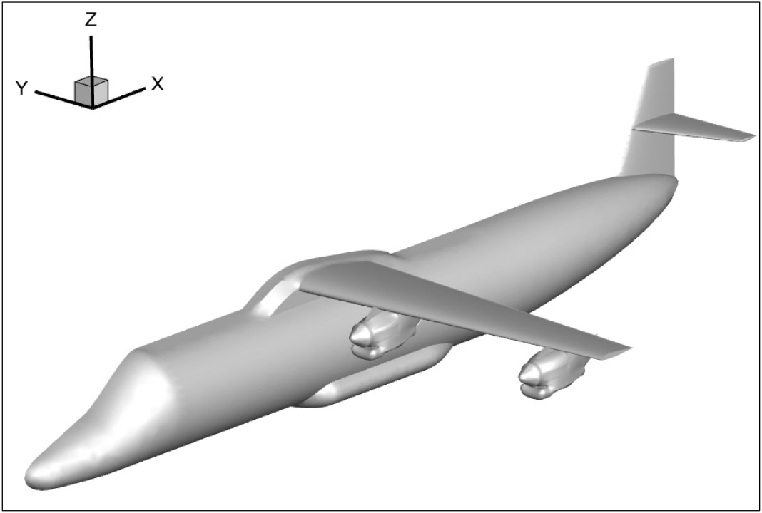
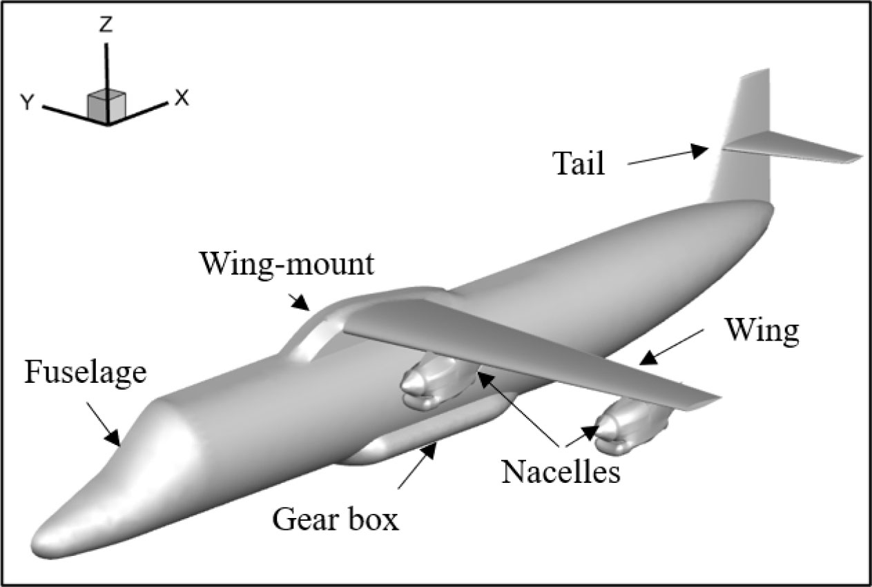
In response to this gap, the present study performs a detailed aerodynamic analysis of a hydrogen fuel cell-powered aircraft equipped with five nacelle engines shown in Fig. 1. Using high-fidelity CFD simulations based on steady-state Reynolds-Averaged Navier-Stokes (RANS) equations and the Spalart-Allmaras turbulence model, the study compares five configurations with nacelles placed at different spanwise locations under the wing. Simulations are conducted at a representative cruise condition (altitude 3000 m, freestream velocity 110 m/s). Key aerodynamic coefficients, including lift (CL), drag (CD), and lift-to-drag ratio (L/D), are evaluated to determine how nacelle spanwise placement influences overall flow behavior and aerodynamic efficiency. By isolating the effects of nacelle distribution in a multiple-nacelle layout, the study provides practical insights for optimizing propulsion-airframe integration in future sustainable regional aircraft.
2. Methodology
2.1 Computational Setup and Boundary Conditions
The aerodynamic analysis was performed using steady-state Reynolds-Averaged Navier-Stokes (RANS) simulations to investigate the impact of under-wing nacelle integration on a hydrogen fuel cell (HFC) aircraft equipped with five nacelles along the span. The simulations were conducted using a pressure-based solver in ANSYS Fluent, assuming incompressible, turbulent flow at cruise conditions.
The aircraft was simulated under freestream conditions corresponding to a typical cruise altitude of 3000 m, where the temperature and air density were set to 268.7 K and 0.909 kg/m3, respectively. The freestream velocity was maintained at 110 m/s, representing a low-subsonic regime appropriate for regional-class commuter aircraft.
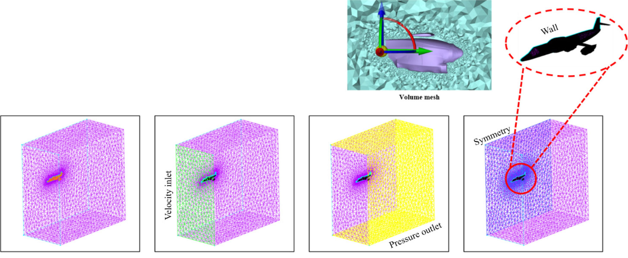
The inlet boundary was defined as a velocity inlet, while the outlet was treated as a pressure outlet. A symmetry boundary condition was applied along the mid-span plane of the aircraft to reduce computational cost. All wall surfaces, including the fuselage, wings, and nacelles, were modeled as no-slip. Gravitational effects and compressibility were neglected due to the relatively low speed and altitude of operation.
The steady incompressible Reynolds-Averaged Navier-Stokes (RANS) equations were solved using a pressure-based finite-volume method in ANSYS Fluent. The continuity and momentum equations were solved for incompressible flow, and viscous effects were included; compressibility was neglected because the freestream Mach number is below 0.35. Turbulence was modeled using the Spalart-Allmaras one-equation turbulence model. Second-order upwind spatial discretization was used for momentum and turbulence quantities, and pressure-velocity coupling employed the SIMPLE algorithm. Convergence was monitored via residuals and integrated force coefficients; all cases were advanced until residuals fell below 10-6 and monitored forces stabilized. The equations are expressed below in Equations (1), (2), (3).
In the governing equations, and are the instantaneous velocity components in the and directions, is time, and is the spatial coordinate in the -direction. Here, 𝜌 denotes the fluid density, is the pressure, 𝜈 is the kinematic viscosity, represents the Reynolds (turbulent) stress components, is the specific enthalpy, is the temperature, and and correspond to the molecular and turbulent thermal conductivities. The numerical solution used a cell-centered finite volume method (FVM) with a steady-state pressure-based solver. Spatial discretization was performed using a second-order upwind scheme, and turbulence was modeled using the Spalart-Allmaras one-equation model. The Spalart-Allmaras (SA) model was adopted for all simulations due to its proven efficiency and accuracy for external aerodynamic flows at low to moderate angles of attack. The SA model performs reliably for attached boundary layers and mildly separated flows, making it well-suited for aircraft configuration studies where the primary interest lies in integrated aerodynamic forces. The present configurations operate at cruise conditions with a Mach number below 0.35 and small incidence, where large-scale separation is not expected. While two-equation models such as k-ω SST can capture more complex stall or separation phenomena, their additional cost is not justified for the current parametric study focused on relative drag contributions. Nevertheless, it is acknowledged that future work involving powered nacelle-wing interactions or higher-incidence conditions may benefit from model comparison with k-ω SST for enhanced prediction of separated wakes.
2.2 Meshing Strategy and Post-Processing
The computational domain was discretized using a hybrid mesh consisting of unstructured tetrahedral elements in the far-field volume and layers near the solid surfaces to resolve the boundary layer accurately. Particular attention was given to the wing, fuselage, nacelle surfaces, and nacelle-wing junctions, where high gradients are expected. Inflation layers were applied with a first-layer thickness corresponding to y+ ≈ 50, ensuring compatibility with the wall-function treatment of the Spalart-Allmaras model. A total of 15 inflation layers with a growth rate of 1.2 were used to capture the near-wall velocity gradient and ensure a smooth transition to the outer mesh. The domain grid is depicted in Fig. 2.
3. Analysis Model
3.1 Atmospheric Model
The International Standard Atmosphere (ISA) model was adopted for the aerodynamic analysis to define the freestream conditions. The selected cruise altitude is 3,000 meters (approximately 10,000 feet), representing regional short-haul operations. Corresponding atmospheric conditions were extracted: freestream temperature T∞=268.65 K, pressure P∞=70.12 kPa, and density 𝜌∞=0.909 kg/m3. The freestream velocity was set to V∞=110 m/s, placing the flow in a subsonic, incompressible regime with a Mach number below 0.35. The flow was assumed steady and fully turbulent for all configurations.
In general, a small positive angle of attack (typically around 2°) is considered for cruise conditions to represent the lift required in level flight. However, in this study, an angle of attack of 0° was adopted for simplicity. Preliminary checks confirmed that this assumption does not introduce significant differences in the aerodynamic coefficients for the present configuration, while it helps streamline the numerical setup and provides a clearer basis for comparing the influence of design parameters. Furthermore, the wing geometry was sized such that sufficient lift is available at the chosen cruise condition, thereby validating the adequacy of the 0° angle of attack assumption.
3.2 Aircraft and Nacelle Configuration
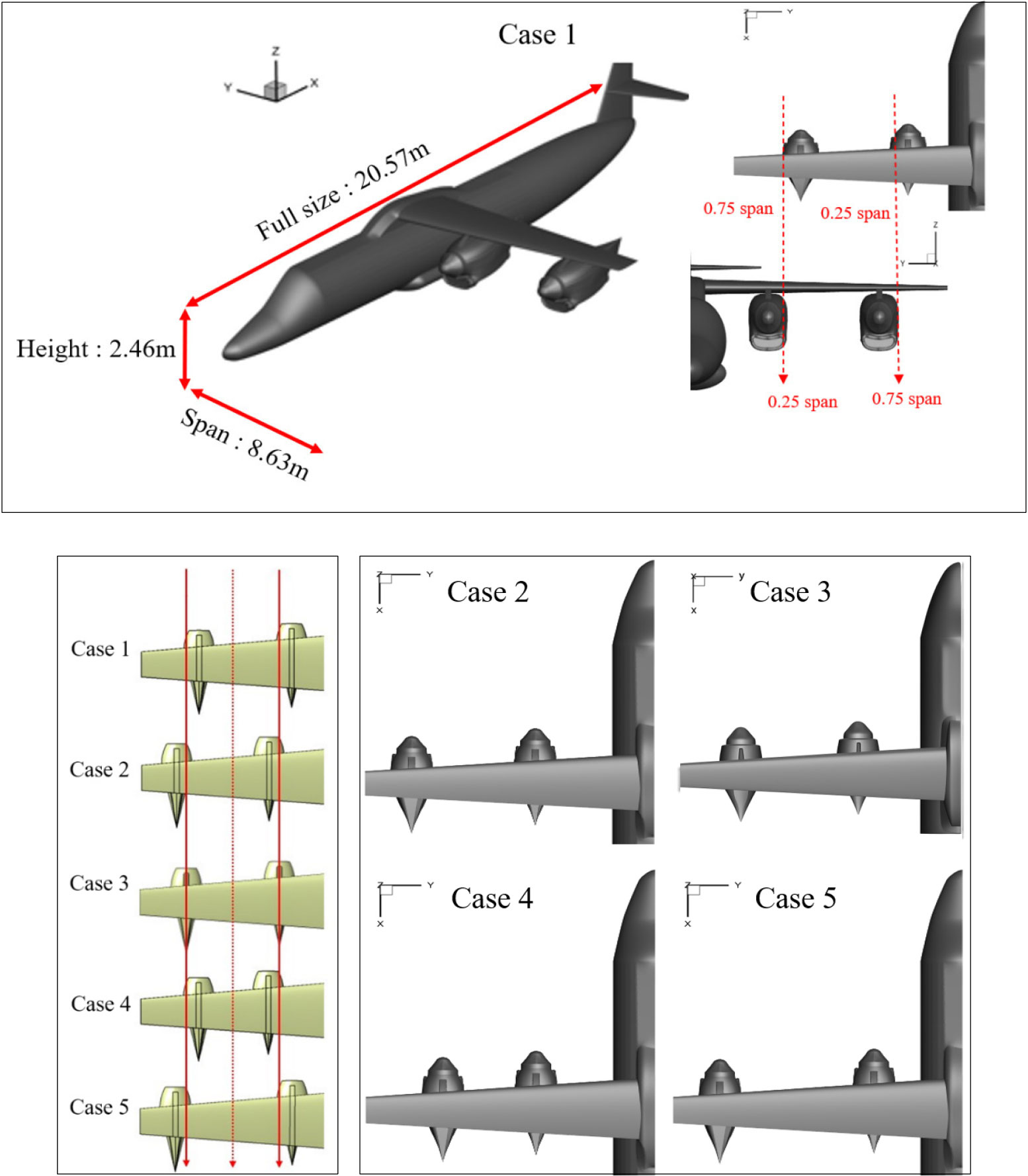
This study investigates the aerodynamic influence of nacelle spanwise placement in a hydrogen fuel cell (HFC) aircraft. A total of five distinct nacelle configurations were evaluated, each derived from a common baseline geometry consisting of a streamlined fuselage, high-efficiency tapered wing, and symmetric under-wing nacelles.
The baseline case (Case 1) features two nacelles mounted beneath the wing along 20% and 70% of the wing span, measured from the root chord along the tip chord, both located within the inner region of the span. This configuration serves as the reference for evaluating the aerodynamic sensitivity to changes in nacelle placement.
In the subsequent four cases (Cases 2 to 5), the nacelles were progressively shifted outward and inward along the wing span to assess how spanwise positioning affects the flow field and aerodynamic performance. Each configuration retains the same nacelle size, pylon design, and distance from the wing surface to isolate the impact of spanwise location alone. Case 2 shifts both nacelles slightly outboard, placing them just beyond the 25% and 75% span stations. Case 3 positions the nacelles symmetrically at the 25% and 75% locations. Case 4 shifts both nacelles inward toward mid-span, placing them just inside the 25% and 75% span. Case 5 introduces an asymmetric configuration in which one nacelle is moved inboard just before the 25% span, while the other is moved outboard just beyond the 75% span.
Fig. 3 illustrates the five nacelle configurations analyzed. The red solid and dotted lines represent the spanwise displacement from the baseline reference positions. All configurations maintain geometric and mesh consistency, allowing direct comparison of lift coefficient (CL), drag coefficient (CD), and derived lift-to-drag ratio (L/D). In addition to force coefficients, pressure coefficient, and velocity magnitude contours were extracted to understand localized flow behavior, including interference patterns near the wing-nacelle junctions.
This parametric study provides insight into the aerodynamic consequences of nacelle positioning in HFC aircraft and supports early-stage design decisions involving nacelle integration strategy.
4. Grid Independence Study and Solution Convergence
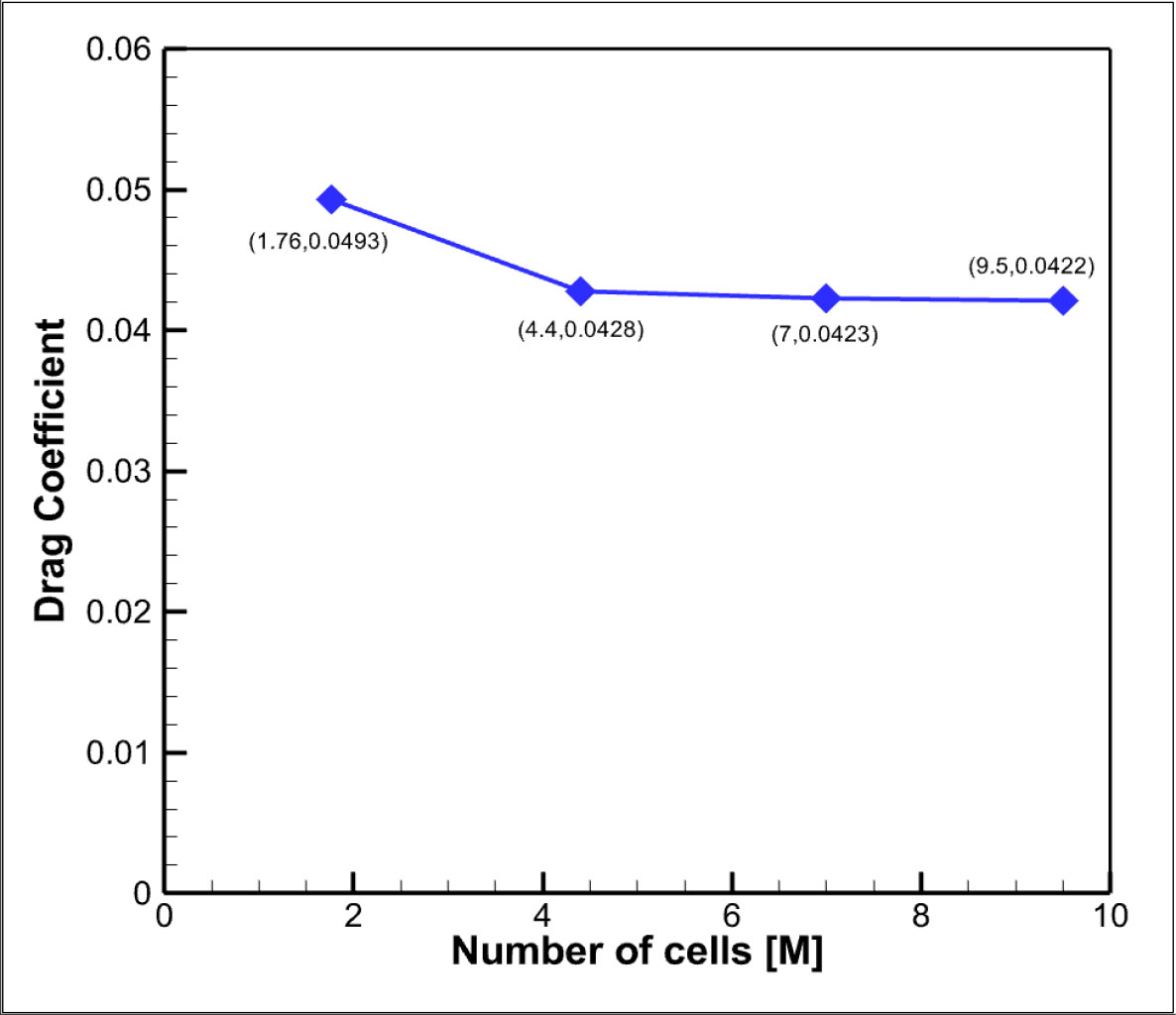
In computational fluid dynamics (CFD) analyses, it is essential to demonstrate that the predicted aerodynamic characteristics are not unduly influenced by mesh resolution. To this end, a systematic grid independence study was conducted before the main simulations. Four volumetric meshes were generated containing approximately 1.76 million, 4.4 million, 7.0 million, and 9.5 million cells.
The drag coefficient (CD) was selected as the principal measure of sensitivity, since it integrates viscous and pressure effects and is directly affected by near-wall resolution and wake refinement. Fig. 4 illustrates the variation of CD with mesh size. A substantial difference was observed when refining from the coarse 1.76 M mesh to the 4.4 M mesh, indicating that the coarse grid under-resolved key aerodynamic features. However, further refinement to 7.0 M and 9.5 M cells produced only marginal variations in CD, with the difference between the 4.4 M and 7.0 M cases remaining below 2%. This trend confirms that the solution approaches asymptotic grid convergence beyond the 4.4 M mesh.
While the 7.0 M and 9.5 M meshes provided slightly finer resolution, the gain in accuracy was negligible compared to the substantial increase in computational cost. For example, doubling the number of cells from 4.4 M to 9.5 M approximately doubles the memory demand and simulation time, which would be prohibitive for conducting the extensive set of parametric simulations required in this study. Therefore, the 4.4 M mesh was chosen as the baseline for the main analysis, striking a practical balance between accuracy and efficiency. To confirm the robustness of this choice, a representative case was recomputed on the 7.0 M mesh, and the results showed no meaningful change in the integrated aerodynamic coefficients.
The steady pressure-based RANS solver converged reliably for all nacelle configurations. Convergence was assessed using a combination of residual decay and the temporal behaviour of integrated aerodynamic force coefficients. For each simulation, the continuity, momentum, and Spalart-Allmaras turbulence residuals decreased by three to four orders of magnitude, reaching values below 10-5. In addition, the monitored lift and drag coefficients reached statistically stationary states. For attached-flow cases, the aerodynamic coefficients approached a steady plateau with variations below 0.1-0.2% over the final 300-500 iterations. For configurations exhibiting mild trailing-edge separation (notably Case 5), the force coefficients displayed bounded periodic oscillations, as expected for separated flows. However, their time-averaged values remained stable, indicating convergence in the time-averaged sense. The use of pseudo-transient marching and appropriate under-relaxation ensured stable and physically consistent solutions. Therefore, the steady RANS solutions reported in this study are considered well converged and suitable for reliable comparison of relative aerodynamic performance trends between the different nacelle configurations.
5. Result and Discussion
The aerodynamic performance of hydrogen fuel cell (HFC) aircraft configurations with under-wing nacelles placed at five different spanwise positions is presented in this study. Using steady-state Reynolds-Averaged Navier-Stokes (RANS) simulations with the Spalart-Allmaras turbulence model, key aerodynamic coefficients, lift (CL), drag (CD), and lift-to-drag ratio (L/D) were extracted, and their trends were analyzed across nacelle positions. In addition, pressure coefficient (Cp) and velocity contours were studied to visualize flow structures and nacelle-wing interactions. The results provide insight into how spanwise nacelle placement affects aerodynamic efficiency in multi-engine HFC aircraft configurations.
5.1 Aerodynamic Coefficients and Global Trends
The comparative analysis of lift coefficient (CL), drag coefficient (CD), and lift-to-drag ratio (L/D) across five nacelle spanwise positions reveals clear aerodynamic trends, as shown in Fig. 5. These trends are visualized in the accompanying bar charts, offering a direct comparison of how each configuration affects global aerodynamic performance.
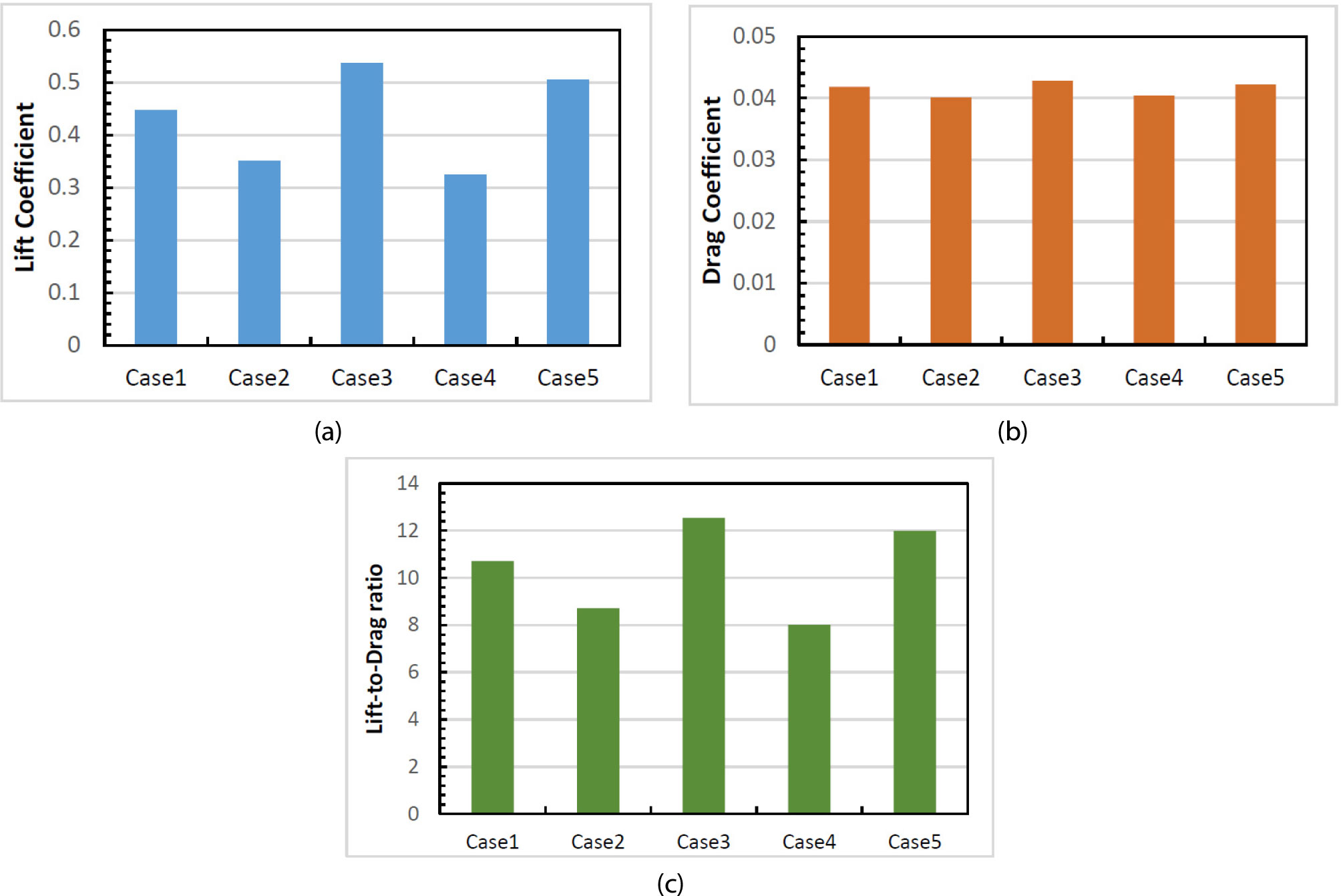
Case 3 configuration, in which nacelles are located symmetrically near 25% and 75% of the span, exhibits the highest lift-to-drag ratio, indicating a well-balanced integration strategy. The CL achieved is also among the highest, highlighting efficient lift production with minimal disruption to spanwise flow.
Interestingly, Case 5, with nacelles positioned farther outboard, achieves an L/D ratio nearly equivalent to the baseline configuration. This outcome may result from reduced nacelle-fuselage interference and more favorable spanwise pressure recovery. Although drag slightly increases, lift retention improves due to more uniform flow development across the mid-to-outboard wing sections.
In contrast, Cases 1, 2, and 4, representing progressively outward nacelle placement, show a consistent decline in lift. Although there is a small reduction in CD in some of these cases, it is insufficient to offset the loss in lift, leading to a marked deterioration in L/D. Case 4, with the nacelles placed tightly around mid-span, results in the poorest aerodynamic performance.
These findings underscore the sensitivity of overall aerodynamic performance to nacelle spanwise placement. While inboard locations offer more favorable flow conditions due to fuselage-accelerated flow and controlled interference, outboard positions compromise lift by disturbing key flow regions and weakening wing effectiveness.
5.2 Pressure Distribution and Wing-Nacelle Interference
In the baseline configuration (Case 1), where nacelles are symmetrically positioned at approximately 20% and 70% of the wing span, the pressure coefficient contours (Fig. 6, 7) display an aerodynamically balanced distribution. A consistent suction peak is visible near the leading edge of the wing, while the nacelles introduce moderate low-pressure regions around their pylons. The downstream pressure field remains relatively uniform and symmetric, suggesting minimal interference and stable flow attachment conditions that correspond with a reasonable lift-to-drag (L/D) ratio for this baseline.
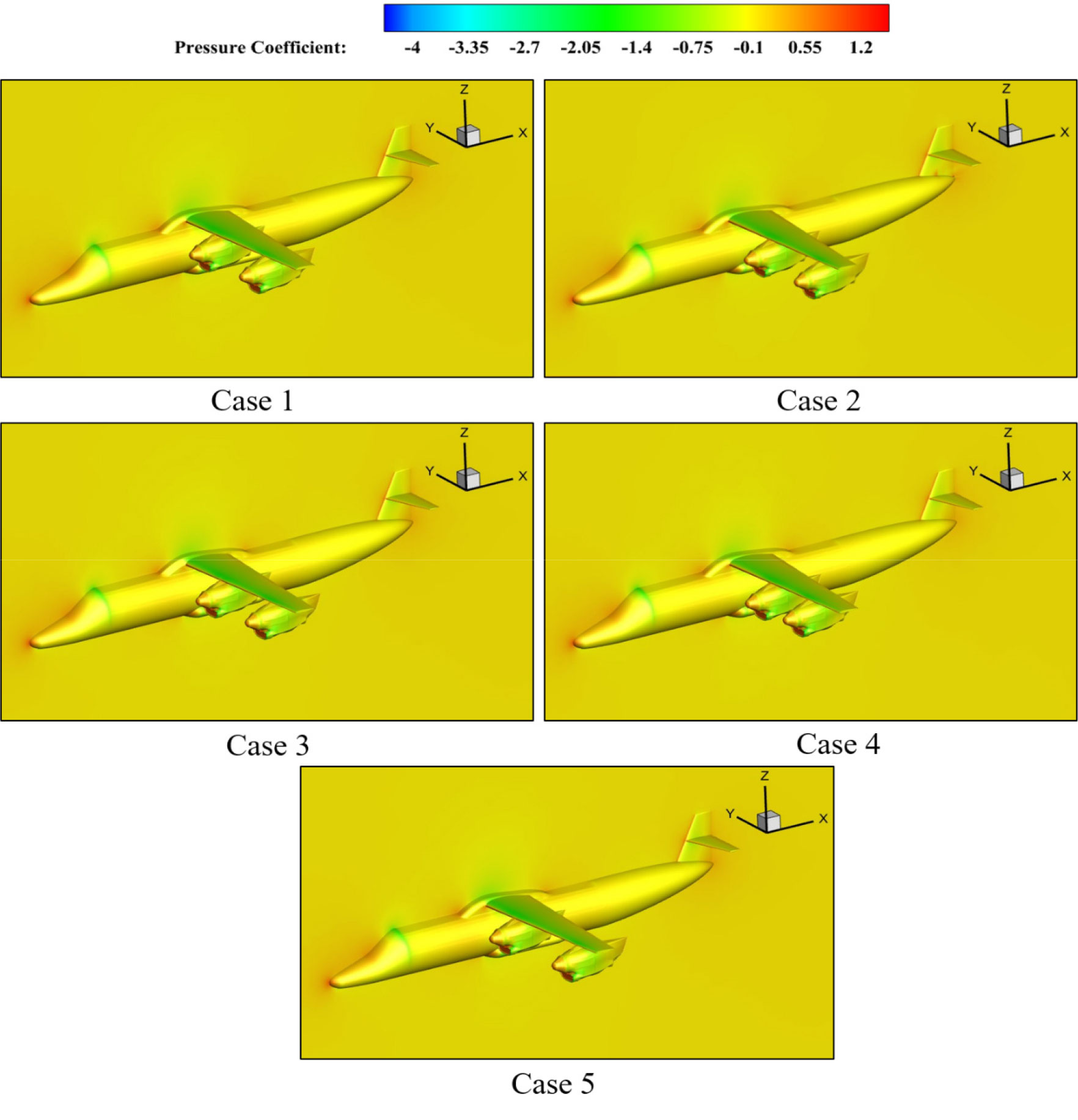
When nacelles are placed further outboard in Case 2, the pressure distribution remains generally smooth, especially over the mid-span and outer wing regions. The suction peaks over the nacelle surfaces appear moderate, and the pressure recovery along the wing is coherent. Although the visual changes are subtle compared to Case 1, pressure recovery appears marginally less coherent along the span. These changes align with a modest decrease in aerodynamic efficiency.
In contrast, Case 3, with nacelles located nearer to the mid-span at 25% and 75% of the span, exhibits intensified low-pressure zones around the nacelles and more pronounced pressure variation near the wing-nacelle junction. The closer spacing appears to disturb the pressure field slightly more, introducing minor asymmetries and potentially increasing interference drag. While the contours may still seem similar at first glance, the overall aerodynamic performance improves further in terms of lift, but with a trade-off in slightly higher drag, resulting in the best L/D among the considered configurations.
The most notable aerodynamic penalty is observed in Case 4, where the nacelles are placed close to the mid-span, near each other. Although no dramatic contour changes are visually evident, this configuration exhibits slightly intensified low-pressure zones near the nacelles and a somewhat disrupted pressure field across the wing. The proximity of the nacelles may have led to mutual wake interference and localized flow instability, which likely contributed to the lowest lift and L/D values of all cases. This underperformance is more convincingly captured in the aerodynamic data.
In Case 5, where nacelles are positioned at the furthest outboard spanwise locations, the pressure distribution appears well-structured and coherent. The low-pressure regions around each nacelle are symmetric and contained, with smooth spanwise pressure gradients along the wing. Although the differences from the baseline are not sharply visible, the aerodynamic results suggest improved flow recovery and reduced interference, culminating in an L/D ratio nearly equal to Case 3. These findings suggest that well-separated nacelle placements, even near the wingtip, can maintain aerodynamic integrity if wake interference and tip vortex amplification are minimized.
5.3 Velocity Field Analysis and Flow Structure Behavior
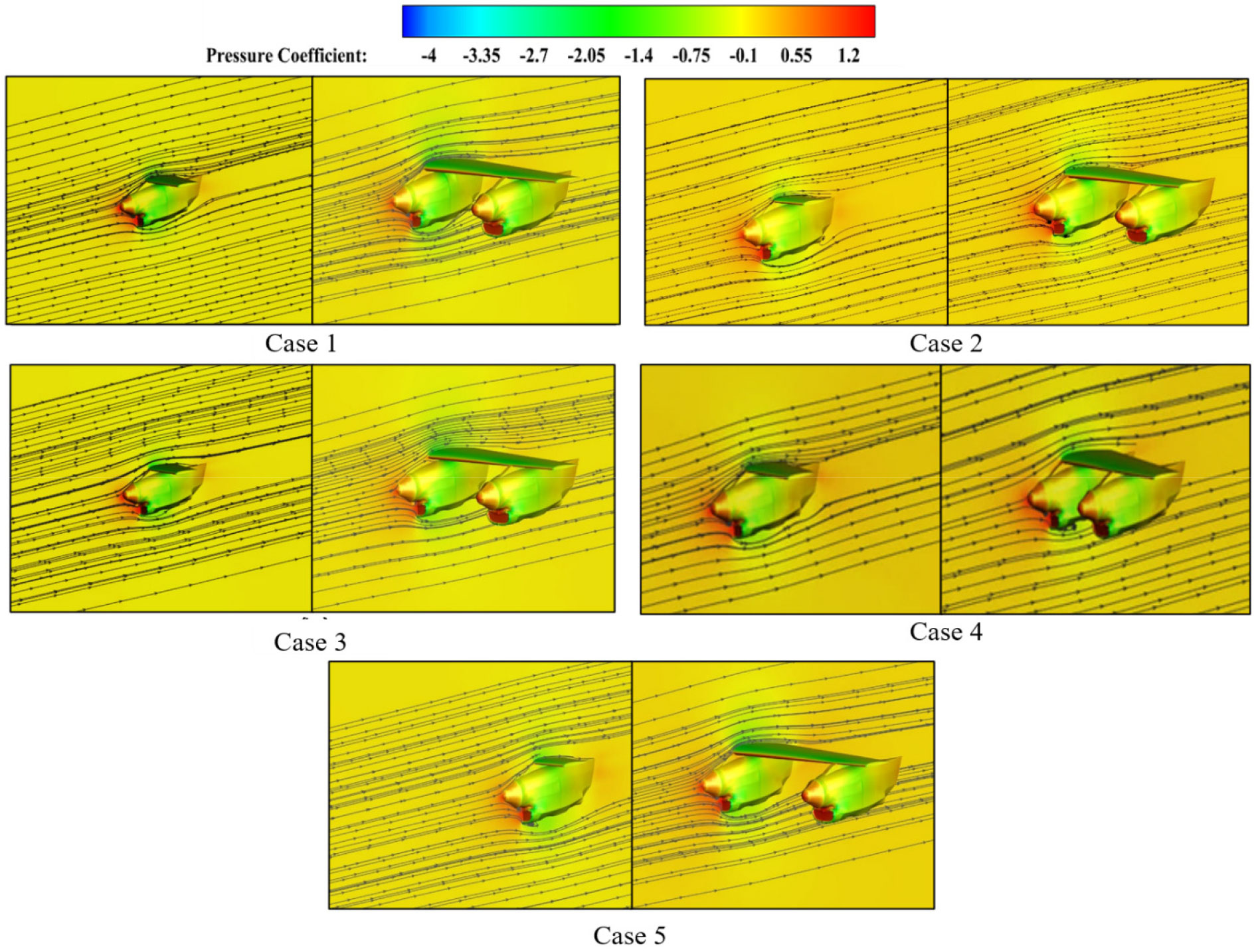
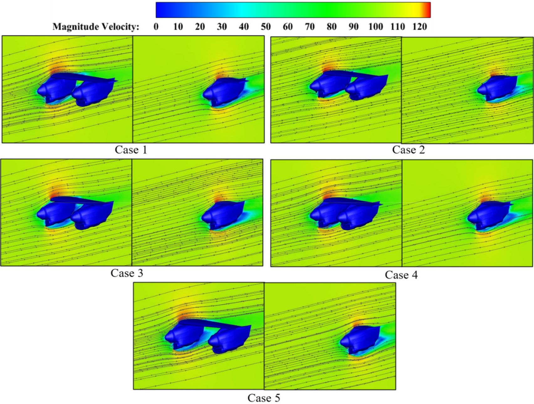
To complement the pressure coefficient analysis, the velocity fields obtained from RANS simulations for five different nacelle placement configurations provide additional insights into the flow behavior around the wing and nacelle during cruise conditions, with particular focus on the near-field wake and interaction regions.
Fig. 8 presents the combined pressure and velocity fields in the immediate vicinity of the nacelles, providing insight into nacelle-wing interference effects. Panel (a) shows the pressure contours with streamlines, while panel (b) shows the corresponding velocity magnitude distribution.
The flow behaviour in these regions is governed primarily by the nacelle-induced pressure field, which alters the local acceleration zones, stagnation regions, and wake development. These changes directly influence the aerodynamic performance metrics, as reflected in the lift, drag, and lift-to-drag ratio data.
In Case 1, the incoming flow approaches the nacelle with relatively uniform alignment, producing moderate acceleration along the surface and a stable, symmetric wake downstream. The wake exhibits limited lateral spread, promoting steady lift production. The L/D value is moderate, suggesting that while drag is not excessive, lift generation is less than the most optimal configurations.
Case 2 shows a stronger inward deflection of the incoming streamlines, which causes the flow entering the nacelle to be asymmetric and unevenly distributed. This non-uniform inlet condition increases the pressure variation across the nacelle, reducing its aerodynamic efficiency. As a result, the wake behind the nacelle is broader and has a larger low-velocity deficit. The persistent wake and the additional cross-flow interference disturb the nearby wing flow, weakening its lift production. Although the drag level is slightly lower than in some other configurations, the substantial loss in lift leads to one of the lowest L/D ratios among all cases.
Case 3 maintains very good alignment of the incoming flow with the nacelle axis, allowing the air to accelerate smoothly above and below the nacelle. This results in a narrow, well-formed wake that contracts rapidly and recovers velocity more quickly downstream. The reduced flow separation also benefits the pressure recovery on the wing surface, enhancing lift production. The clean inflow and stable wake structure allow this case to achieve the highest lift and the best L/D ratio, clearly showing the aerodynamic advantages of balanced nacelle positioning.
Case 4, with nacelles positioned close to the mid-span, experiences significant upstream flow distortion and strong cross-flow effects, particularly on the inboard side of the nacelle. This positioning causes greater interference between the nacelle wake and the wing boundary layer. The wake remains wide and slow to recover, indicating persistent separated flow regions downstream. The disturbed pressure field over the inner wing reduces its effective lift contribution. Even though the drag level is similar to other cases, the severe drop in lift makes this configuration the weakest in terms of aerodynamic efficiency, producing the lowest L/D ratio of all.
A more pronounced separation region is observed in Case 5. This behaviour is attributed to the asymmetric spanwise placement of the two nacelles, which alters the local load distribution across the wing. The outward-shifted nacelle intensifies the local downwash and strengthens the nearby tip vortex. The increased vortex-induced suction on the upper surface promotes earlier boundary-layer separation.
The resulting low-pressure pocket contributes to a noticeable rise in pressure drag and a small reduction in lift compared with the symmetric configurations (Cases 3 and 4). This agrees with classical wing-vortex interaction behaviour, where stronger tip vortices induce additional spanwise flow and accelerate the onset of separation near the trailing edge. The merged pressure/velocity field in Fig. 8 clearly illustrates this mechanism, showing both the enlarged separated zone and the corresponding velocity deficit.
Overall, the velocity field results confirm that nacelle spanwise placement has a major effect on local flow structures, wake development, and downstream aerodynamic behavior. Configurations that keep the inflow symmetric and allow the wake to contract and recover quickly, such as Cases 3 and 5, achieve higher lift and improved aerodynamic efficiency. In contrast, arrangements that produce asymmetric inflow and maintain large, slow-recovering wakes, such as Cases 2 and 4, disrupt wing aerodynamics and result in lower L/D performance.
Following the near-field analysis, Fig. 9 illustrates the global wing-body velocity field, showing how nacelle-induced flow features interact with the larger wing environment. In the baseline Case 1, where nacelles are shifted slightly inboard, there is a minor deflection of streamlines near the nacelle-wing junction. While still largely coherent, the flow behind the nacelles exhibits early signs of interaction with the downstream boundary layer. The wake remains narrow and controlled, which correlates with a configuration offering favorable aerodynamic performance. Case 2 presents nacelles placed further outboard, and the velocity field remains similarly clean. The streamlined curve naturally wraps around the nacelle geometry without visible separation, and wake expansion is minimal. These mild changes are consistent with the small drop in lift-to-drag ratio compared to the baseline. In Case 3, the velocity field is smooth and symmetric, with narrow and stable wake regions trailing each nacelle. The streamlines remain largely undisturbed over the nacelle and wing surfaces, indicating effective attached flow and efficient aerodynamic performance. In Case 4, where nacelles are placed closest to each other near the mid-span, the wakes appear slightly more distorted and broadened compared to other cases. Some streamline divergence is visible, especially between the nacelles, suggesting limited nacelle-nacelle interference. However, flow separation or major wake overlap is not clearly evident, indicating that any aerodynamic penalties likely arise from interactions not strongly visible in this velocity slice. Finally, Case 5, with the most outboard nacelle configuration, maintains a well-organized velocity field. The wakes remain narrow and attached, and the streamlines align well across the wing span. While differences from the baseline are not highly pronounced, this configuration appears to avoid both nacelle-fuselage and nacelle-tip interference, supporting aerodynamic performance nearly equivalent to Case 3.
5.4 Component-Level Drag Contribution Analysis
In addition to the aerodynamic performance evaluation across five nacelle spanwise locations, a component-level analysis was conducted to identify the relative drag contribution of each major aircraft part. The Case 3 configuration is used for all drag comparisons presented in this section. This approach provides a clearer understanding of where nacelle positioning effects are most critical and how they interact with baseline drag sources. Table 1 presents the drag coefficients of each component configuration, where the individual components are identified in Fig. 10, and Fig. 11 visually depicts their relative share of the overall drag.
Table 1.
Drag coefficient contribution of individual components
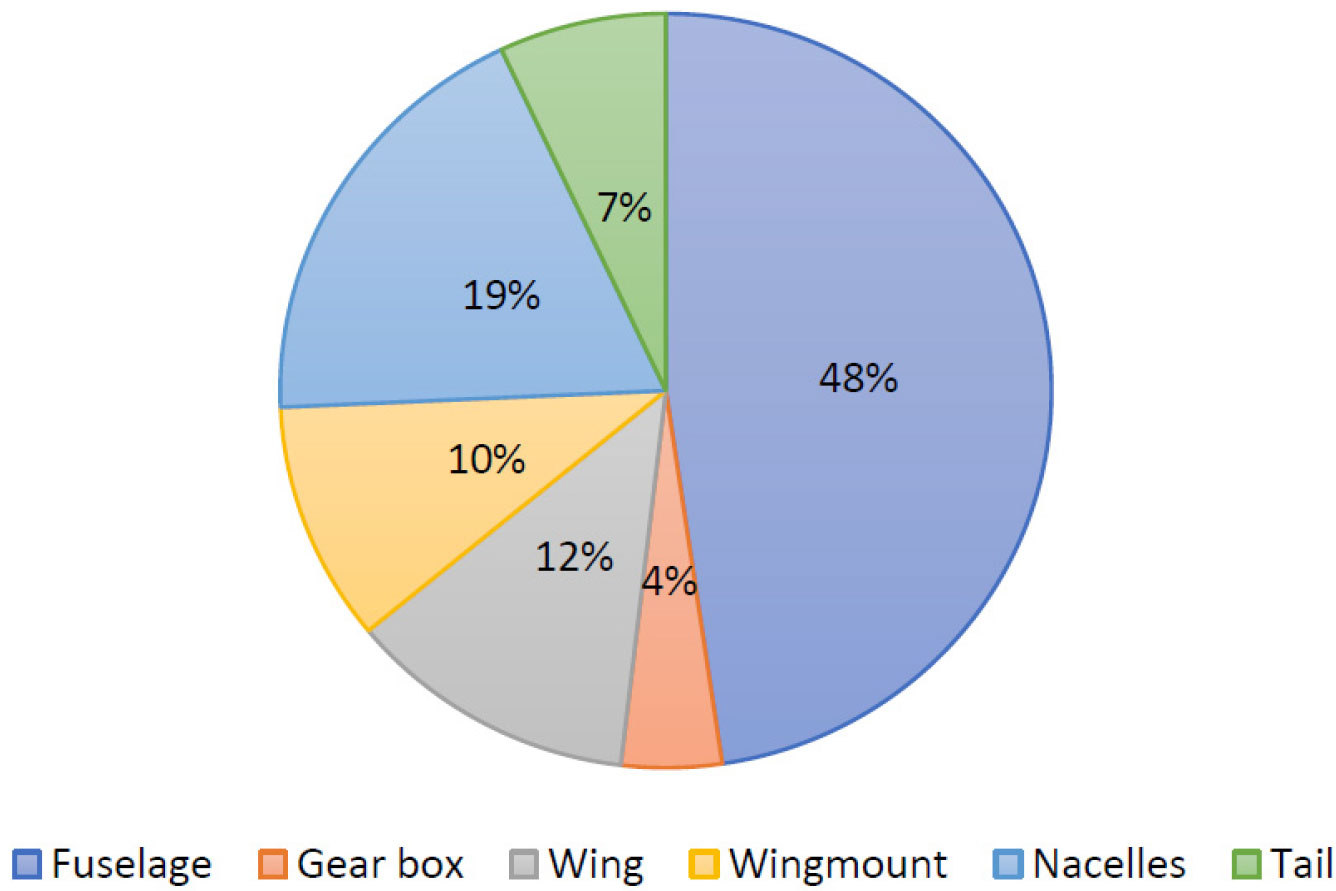
For the baseline configuration (Fuselage, Gearbox, Wing, wing-Mount, Nacelles, Tail), the fuselage emerges as the dominant source of drag, accounting for approximately 48% of the total drag coefficient (CD=0.0428). The nacelles and wing, contributing 19% and 12% respectively, represent secondary drag sources, highlighting the influence of both propulsion integration and aerodynamic surfaces on overall performance. The wing mount and tail contribute moderately, at 10% and 7%, whereas the gearbox accounts for the least, at 4%.
The analysis reveals that the fuselage is the dominant contributor to total drag, due to higher wetted area and corresponding interference drag. This emphasizes the critical role of fuselage shaping and surface smoothness in aerodynamic refinement. The nacelles, responsible for approximately 19% of the total drag, also represent a significant aerodynamic penalty. Their contribution underscores the necessity of optimizing nacelle and pylon integration and minimizing interference effects with the wing and fuselage.
Secondary contributors include the wing and wing-mounted structures. While wings are primarily designed for lift generation, their induced drag and the effect of wing-mounted elements on local flow fields contribute appreciably to the overall drag budget. The tail, contributing a relatively minor fraction of 7%, demonstrates its limited but non-negligible influence, particularly in stabilizing flow and mitigating induced drag from upstream components. The gearbox, despite its structural importance, contributes the least to total drag, highlighting the efficiency of its streamlined integration within the overall configuration.
This component-wise decomposition provides critical insights into aerodynamic refinement priorities. Reducing fuselage and nacelle-induced drag offers the most substantial potential for performance gains. Concurrently, careful attention to wing-mounted elements and tail design can yield incremental improvements. Overall, the quantitative breakdown facilitates a focused design strategy, guiding optimization efforts to the most impactful regions of the aircraft, ultimately enhancing performance while maintaining structural and functional integrity.
5.5 Physical Interpretation and Design Implications
The findings of this study reveal the strong influence of nacelle spanwise positioning on the aerodynamic performance of a hydrogen fuel cell (HFC) aircraft. The comparative results demonstrate that neither extreme inboard nor extreme outboard nacelle locations are aerodynamically optimal. Instead, there exists a performance-sensitive window where lift generation, drag control, and wake behavior can be balanced most effectively.
Notably, the poorest aerodynamic performance was observed in Case 4, where nacelles were positioned closest to the mid-wingspan. In this configuration, the nacelle wakes interact directly with the wing boundary layer and adjacent nacelle streamlines, leading to intensified flow interference, poor pressure recovery, and weakened lift generation. The wake structures become wider and more chaotic, degrading the downstream flow environment and resulting in elevated drag. These effects reduce the aerodynamic effectiveness of the inner wing and disrupt overall spanwise lift distribution. This indicates that excessively clustered nacelles near the fuselage impose severe aerodynamic penalties, even if they may appear structurally convenient.
In contrast, Cases 3 and 5, which feature moderately spaced nacelles either symmetrically around 25-75% span or placed at the most outboard positions, delivered the highest lift-to-drag (L/D) ratios. These configurations promoted smoother spanwise pressure gradients, cleaner wake development, and minimized aerodynamic interference, either from the fuselage or from overlapping nacelle wakes. Case 5, in particular, showed that even the most outboard nacelle positions can achieve better performance than the baseline, provided the wakes remain well-aligned and flow separation is avoided.
However, even if Case 1 (baseline) shows favorable aerodynamic efficiency, Cases 2 and 4, where nacelles were placed at different positions with respect to the mid-span, showed degraded aerodynamic efficiency. Case 4, with very tightly-spaced nacelles, exhibited the worst L/D ratio due to increased nacelle-nacelle interference, wake thickening, and distorted flow over the inner wing. Case 1, although slightly better, still suffered from early wake interaction and reduced lift. These results suggest that excessive clustering near the mid-span disrupts wing aerodynamics more severely than well-spaced outboard placements.
These observations suggest that the optimal aerodynamic zone for nacelle placement in a multi-nacelle configuration lies neither too close to the fuselage nor too far toward the wingtip. Instead, there exists a mid-span region where favorable pressure recovery, controlled wake growth, and lift preservation are best achieved. This aligns well with the findings of Cao et al. [12], who identified the 25-29% span range as the most aerodynamically efficient nacelle zone in a transonic transport configuration. Our results extend this understanding to a subsonic regional HFC aircraft, further emphasizing that nacelle spanwise location is not only a structural consideration, but a critical aerodynamic design variable.
While actual nacelle placement must also account for structural, propulsion, and system integration constraints such as load-bearing capacity, cooling duct routing, and hydrogen tank placement, this study reinforces that aerodynamic optimization should guide initial nacelle layout decisions. For future zero-emission aircraft utilizing hydrogen, especially in the regional transport category, carefully tuned nacelle positioning will be essential to achieve both energy efficiency and aerodynamic performance goals.
While the current analysis considers nacelles in a non-powered state, several previous computational studies have demonstrated that integrating active propellers substantially influences aerodynamic behavior. The propeller slipstream increases local dynamic pressure and effectively raises the angle of attack on the wing, thereby enhancing lift generation. However, this lift enhancement often comes at the cost of increased drag, primarily due to higher pressure and viscous effects near the nacelle-wing interface [25,26]. For example, Sánchez-Moreno et al. [26] analyzed cruise and windmilling conditions and found that powered nacelles alter local flow structures and can either improve or impair aerodynamic efficiency depending on the integration strategy. Similarly, van Schoor and Pretorius [27] showed that propeller slipstream interactions significantly affect high-lift device performance, altering separation behavior and wake structure. These findings reinforce that powered nacelle configurations can have complex, configuration-dependent effects on lift-to-drag ratio (L/D), which require careful aerodynamic balancing. Accordingly, if rotating propellers were included in the present configuration study, it is anticipated that Case 3, already optimal in the static condition, might further benefit from propeller-induced flow augmentation. Future work should incorporate actuator disk or full rotating blade models to quantify these interactions and refine nacelle placement strategies.
6. Conclusion
This study presented a comprehensive numerical investigation into the aerodynamic effects of nacelle spanwise placement in a 19-seater hydrogen fuel cell (HFC) commuter aircraft. Recognizing the increasing design flexibility and integration challenges posed by electric propulsion systems, the work specifically focused on evaluating how varying nacelle positions along the wing span influence global aerodynamic performance.
Five distinct under-wing nacelle configurations were analyzed using steady-state Reynolds-Averaged Navier-Stokes (RANS) simulations with the Spalart-Allmaras turbulence model. The configurations were tested under cruise-representative conditions at 3000 m altitude and a freestream velocity of 110 m/s. Aerodynamic parameters such as lift coefficient (CL), drag coefficient (CD), and lift-to-drag ratio (L/D) were compared and supported by detailed pressure and velocity contour analyses.
The results confirmed that nacelle spanwise location plays a decisive role in shaping flow behavior and aerodynamic efficiency. Among the configurations, the symmetrically placed nacelle (Case 3) and widely separated nacelle (Case 5) placements offered the most favorable outcomes, achieving high L/D ratios with stable flow structures and effective pressure recovery. In contrast, excessively inboard nacelle clustering (Case 4) led to pronounced flow disruption and degraded lift generation, highlighting the adverse aerodynamic penalties of placing nacelles too close to each other. These trends emphasize the need for careful nacelle integration strategies in multi-nacelle layouts, where both fuselage and tip-induced flow interactions must be accounted for.
The findings of this study align closely with prior literature, including Cao et al. [12], reinforcing that an aerodynamic “sweet spot” exists for nacelle positioning, typically near 25-30% of the wing span. This optimal region balances interference effects while preserving flow symmetry and lift distribution, providing a valuable guideline for future regional HFC commuter aircraft design. Importantly, the aerodynamic implications identified here offer not only performance benefits but also critical input for systems-level trade-offs in structure, thermal management, and propulsion packaging.
While the current study provides valuable aerodynamic insights into the influence of under-wing nacelle spanwise positioning, several limitations must be acknowledged, which also open pathways for future research. In this work, nacelles were modeled as passive flow bodies without incorporating thrust forces, rotating propellers, or internal intake dynamics. As such, the analysis does not capture the full complexity of propulsion-airframe interactions that are critical in realistic hydrogen-powered aircraft configurations.
Future work will incorporate powered nacelle configurations using actuator disk or rotating blade models to assess propeller-induced aerodynamic augmentation. Transient simulations will also be considered to capture unsteady wake interactions. Moreover, since thermal aspects are critical in the nacelle due to the high heat generation of fuel cells and the need for effective cooling through thermal management systems, future studies will employ compressible RANS equations and couple these aerodynamic analyses with structural constraints, propulsion system integration, and thermal considerations. This multidisciplinary approach will enable a more comprehensive design framework for optimizing hydrogen-powered aircraft configurations.
